 Tweet
Tweet
Originally posted by cirgent
View Post
-
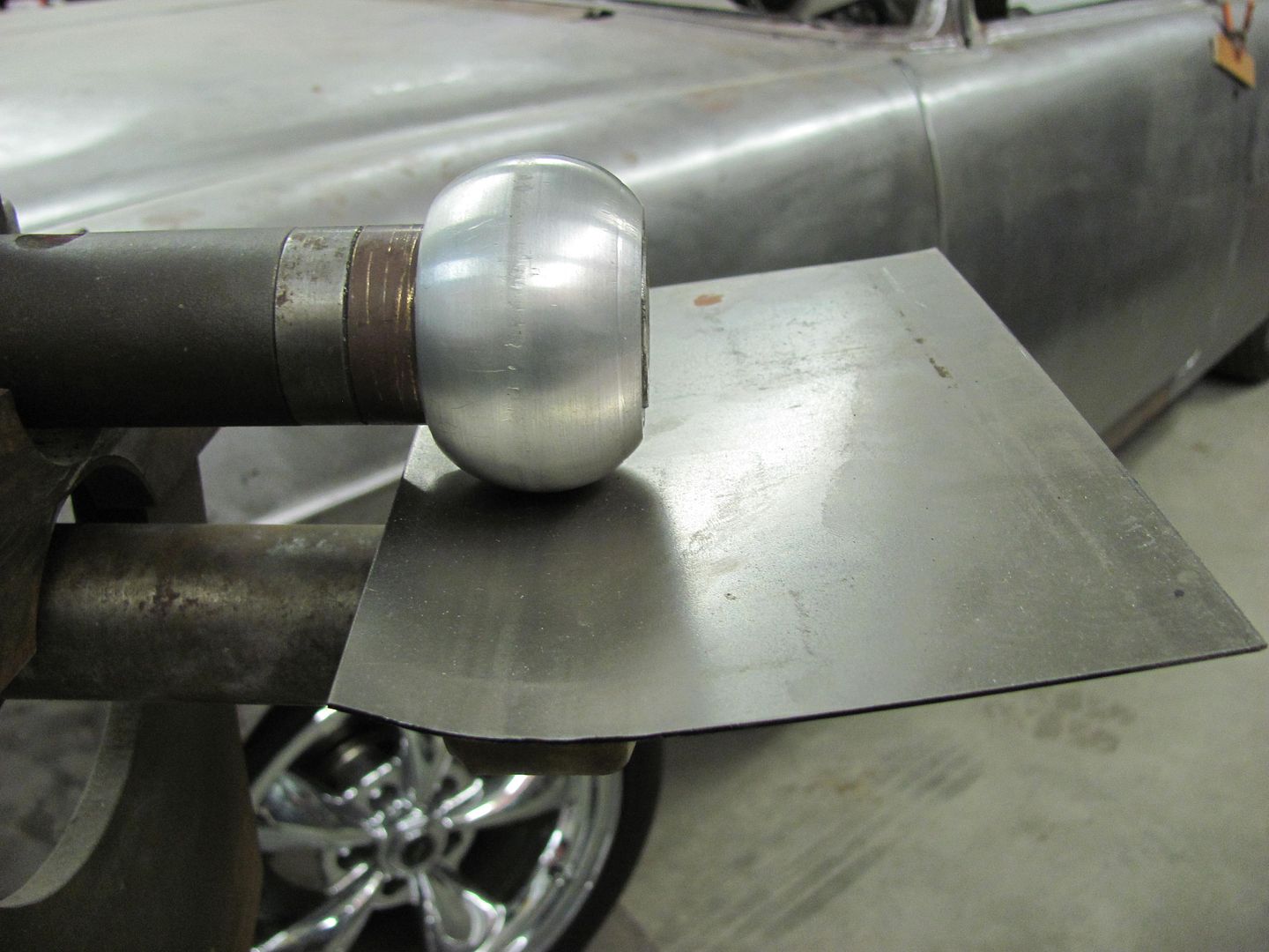
I use that method in some cases, and even though shrinking the flange helps to form the radius in the adjacent panel, anything much over an inch wide will require another forming process afterward to provide the radius consistently across the entire width. As wide as the replacement panel is, shrinking the edges to provide the radius will result in a low area in the middle as that area resists the movement and tries to remain flat. In a panel like the one shown, forming the roll across the panel first, before flanging, helps to form it consistently across the entire width.Last edited by MP&C; December 8, 2012, 08:45 AM. -
Great work Robert, you make it look easy. I know just enough to appreciate how well those panels are formed - i'd have had a sizeable scrap pile before i got close to anything usable.A Carter Carb Shop, sales and serviceComment
-
^^ NO DOUBT!
It brings up the question for me - cold hardening or work hardening, whatever I should call it, if I jack something up really bad can I anneal it and try again?Flying south, with a flock of bird dogs.Comment
-
Work hardening, and thus annealing, is more prevalent when working with alumiinum. Rarely will you find a need for annealing when working with cold rolled steel.Comment
-
You do good work palI BELIEVE IN JOHN 3:16Comment
-
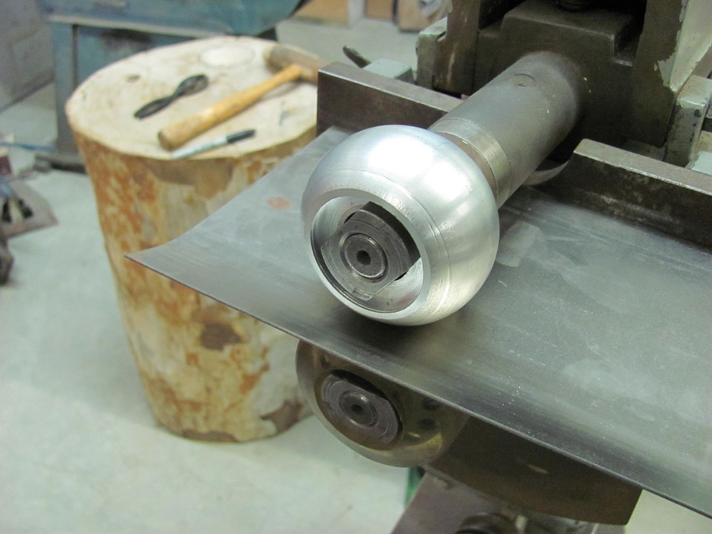
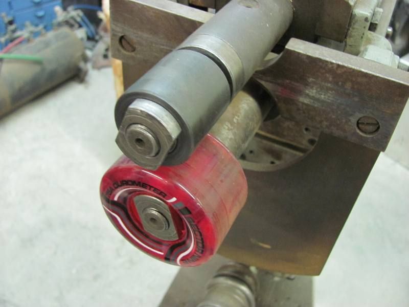
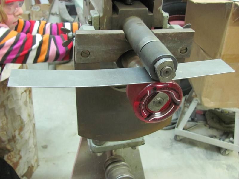
Well after about three months travelling for work, I finally was able to get back out in the shop and get some dust off the lathe today. The last time I used the bead roller I made a dash insert for a Studebaker truck. It had a considerable roll added to it, which was much too tight a radius for using the go kart slick on the wheel.. This was done using the skateboard wheel and a 1/2" wide bead roller
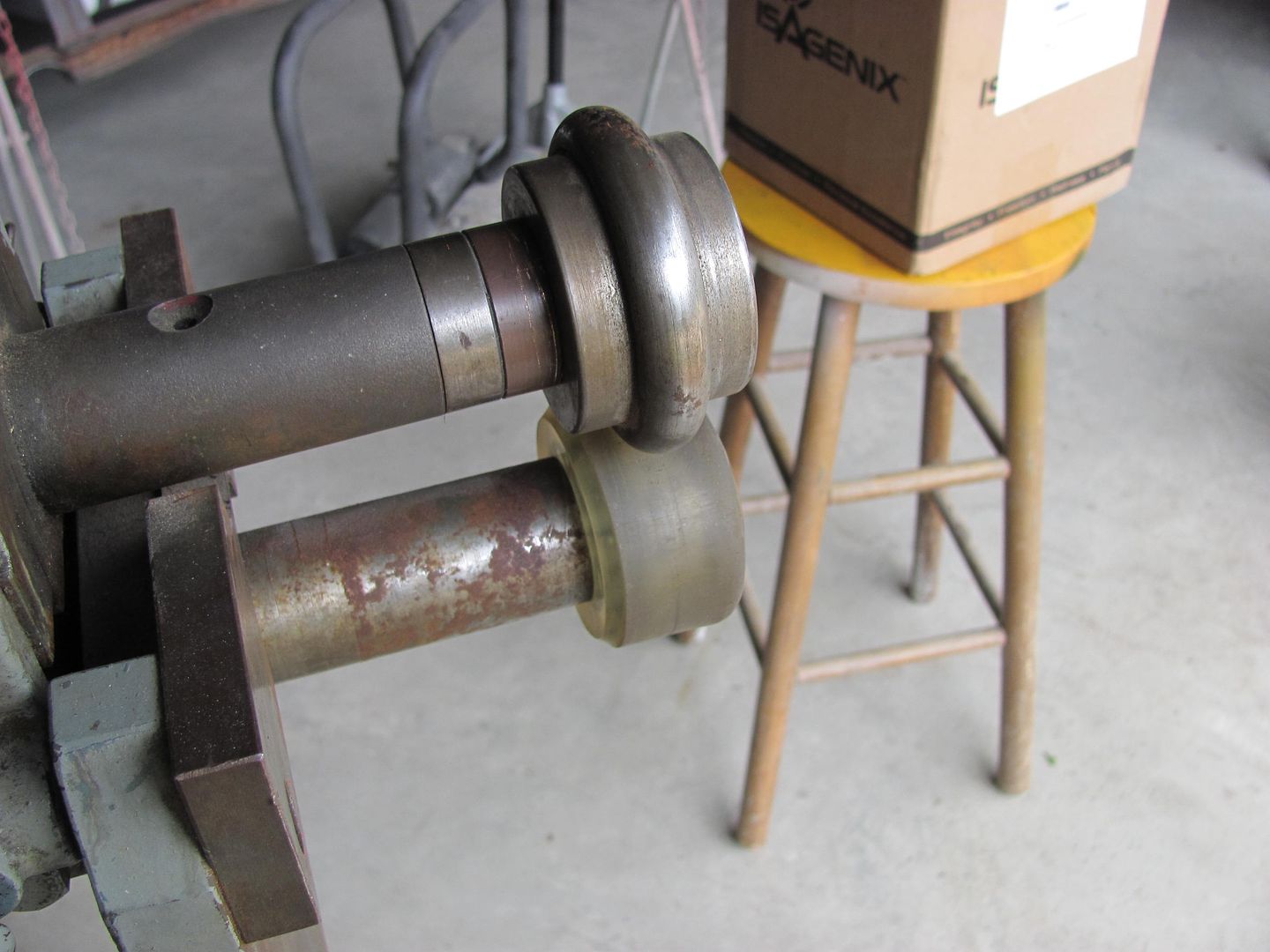


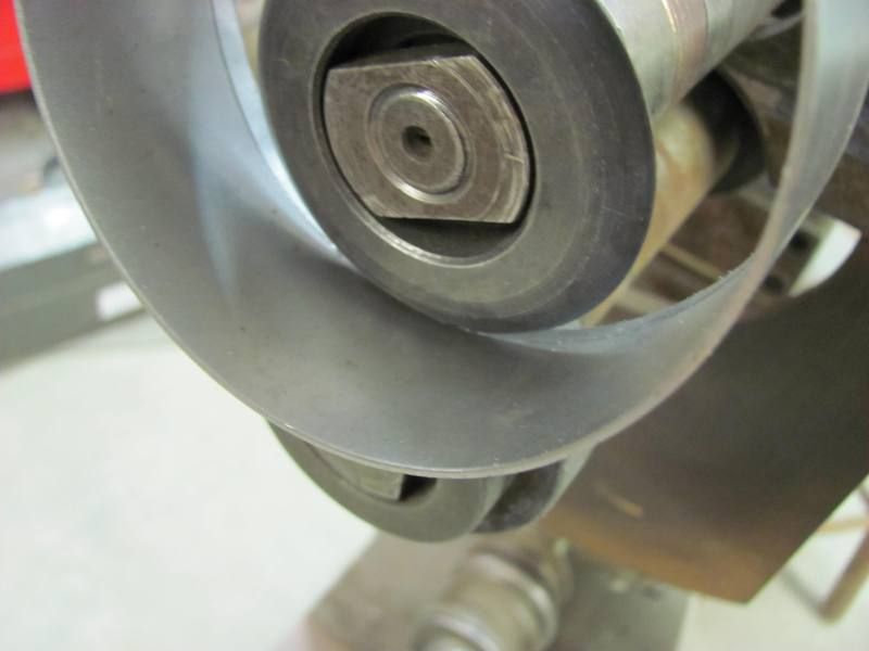
But this seemed to leave pronounced creases from the beading die, and I wanted to replace this with one with a wider radius.
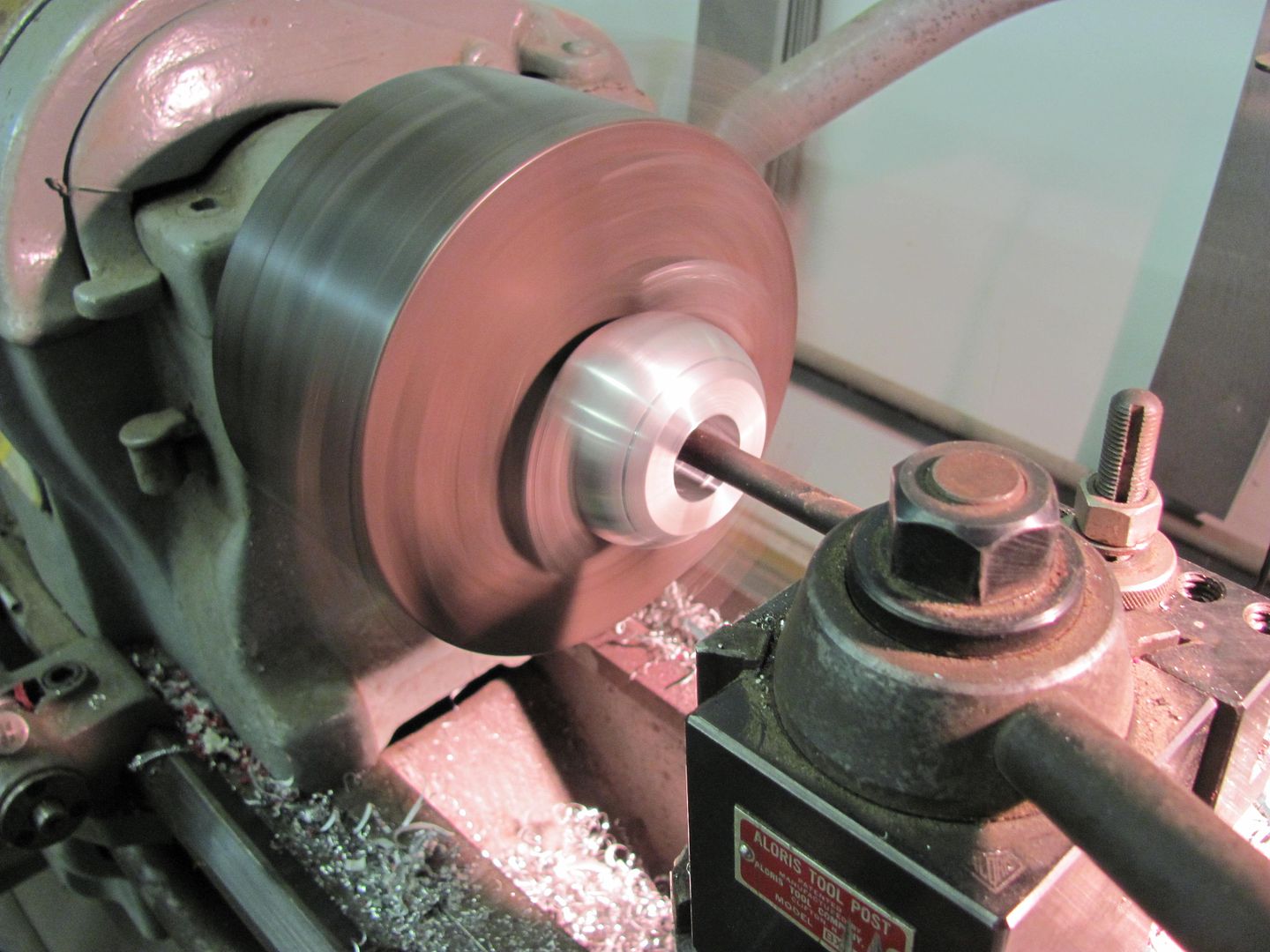
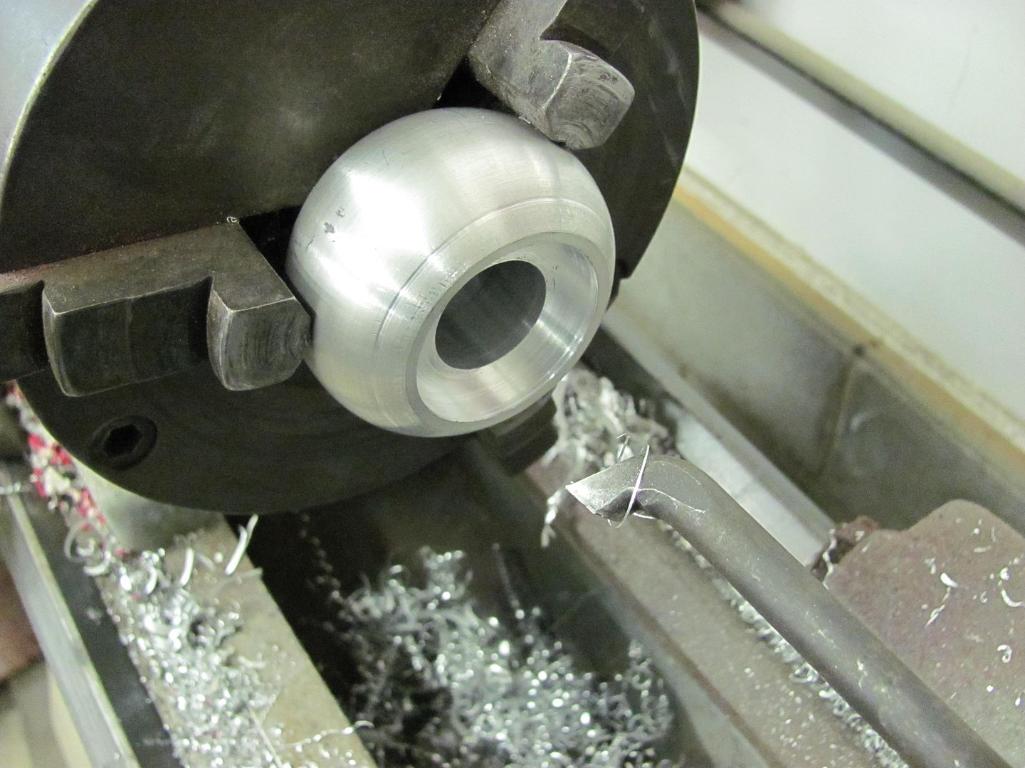
and a relief cut for the shaft nut...
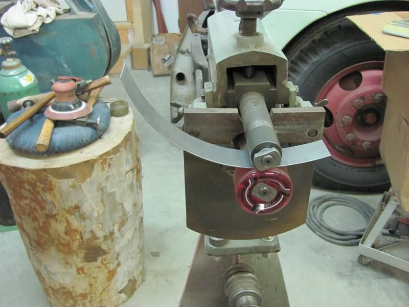
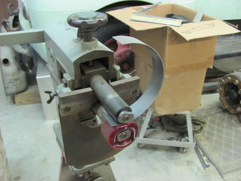
A few passes with some 18 ga......
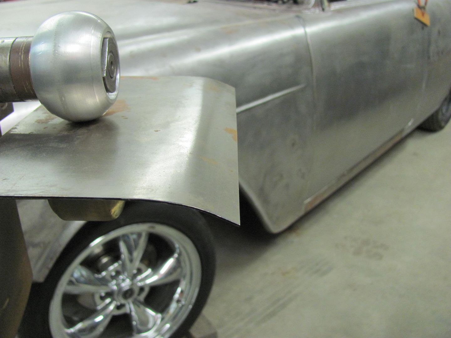
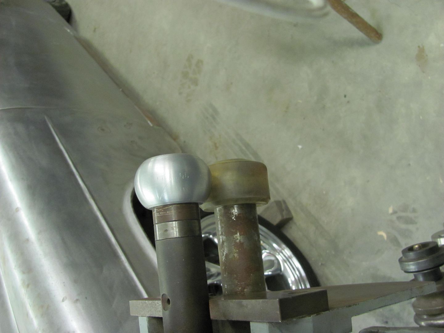
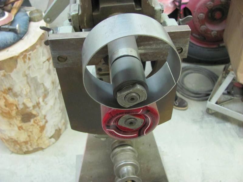
Outside has less noticeable marking.. Yeah, this should work!Comment
-
when I get fired from my current career, I want to push a broom in your shop. I'll do it for free if you'll let me look over your shoulder while you are working.
envious. Flying south, with a flock of bird dogs.
Comment
-
If you saw how dirty the floor is, you may think twice!
Comment
-
You had me when I saw the vintage trucks...my favorites. After seeing your amazing skills, I was inspired! Should be a sticky for all your tutorship and guidance....seriously! Trick of the month type stuff! About to get a skateboard wheel modified soon.Comment
-
x2 on sticky - and I've seen pictures of the floor, I'd still do it. lol.Flying south, with a flock of bird dogs.Comment
-
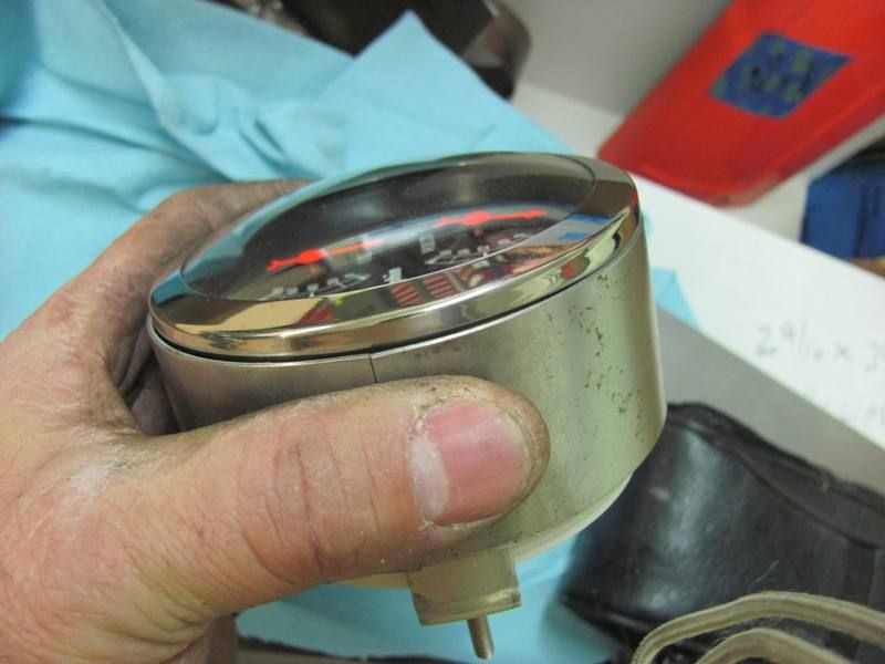
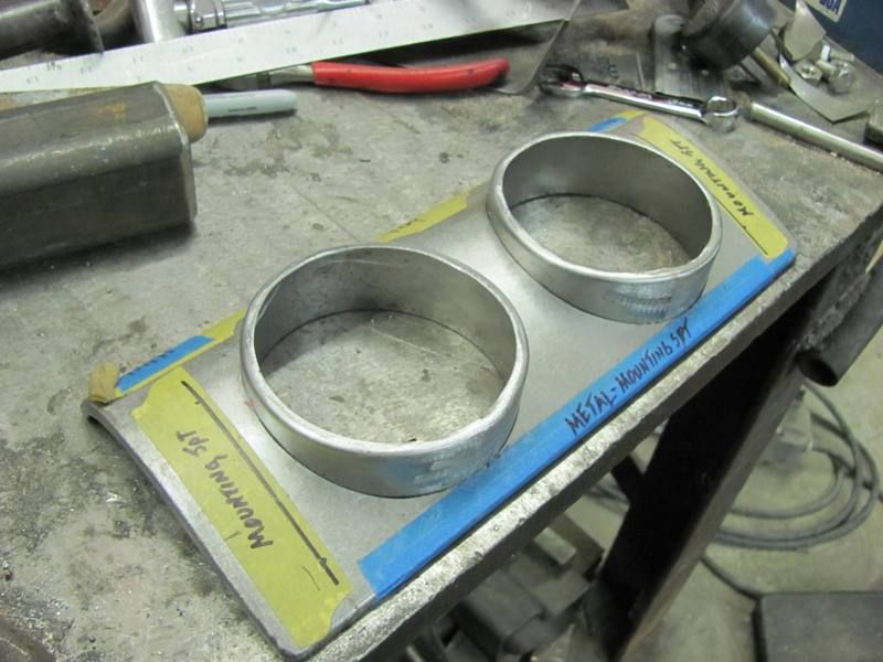
Well the Studebaker owner stopped by recently with the dash pieces I made last summer. He had made up his mind for the dash layout, and received all the gauges. As the panel for the center of the dash has a crown, we will need some adapter rings...
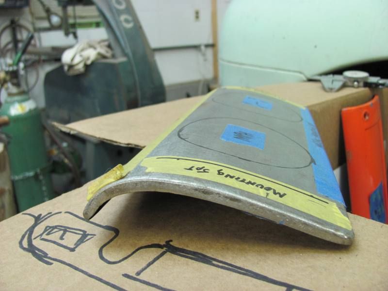
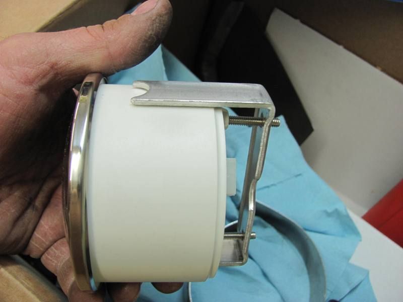
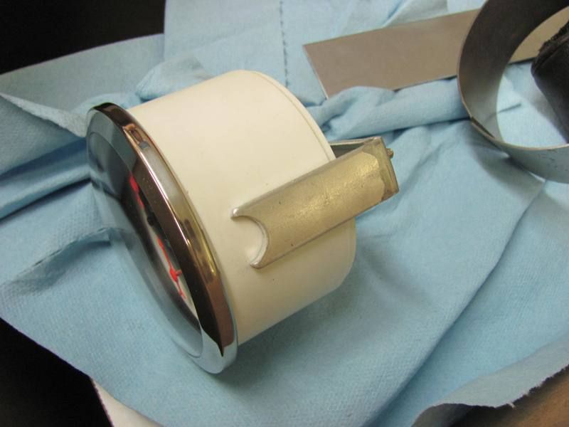
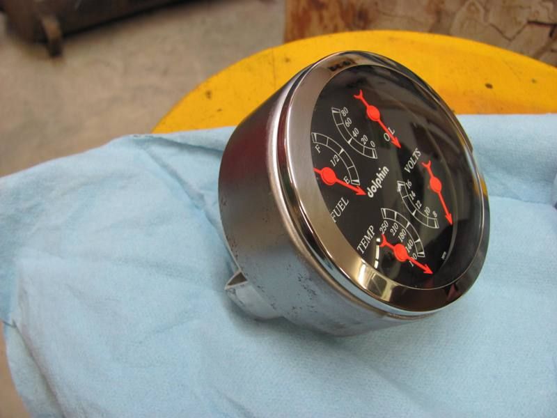
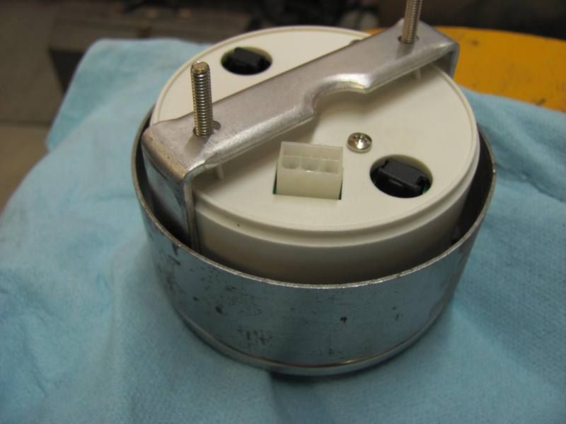
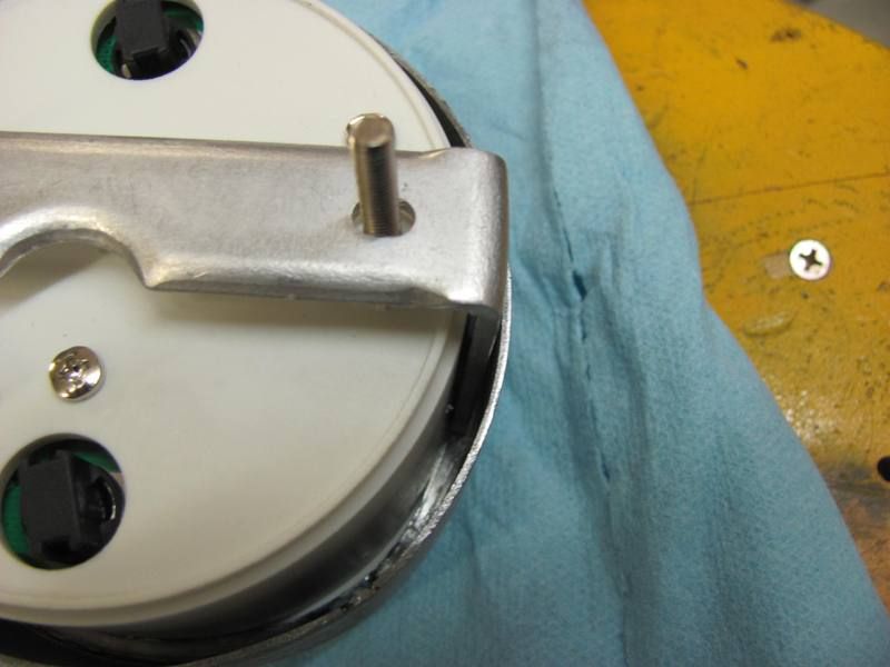
Here's the new gauge with the clamping bracket....
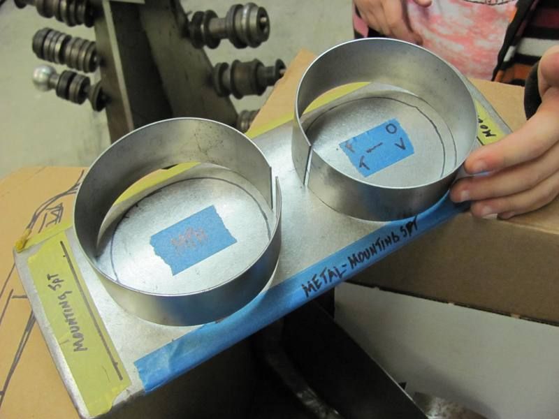
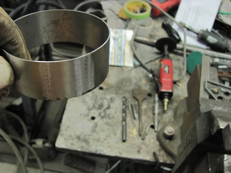
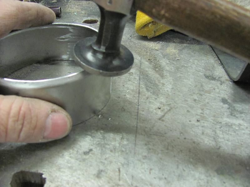
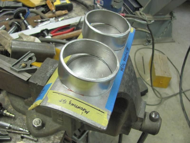
Not having a slip roll, I decided to try these in the bead roller:
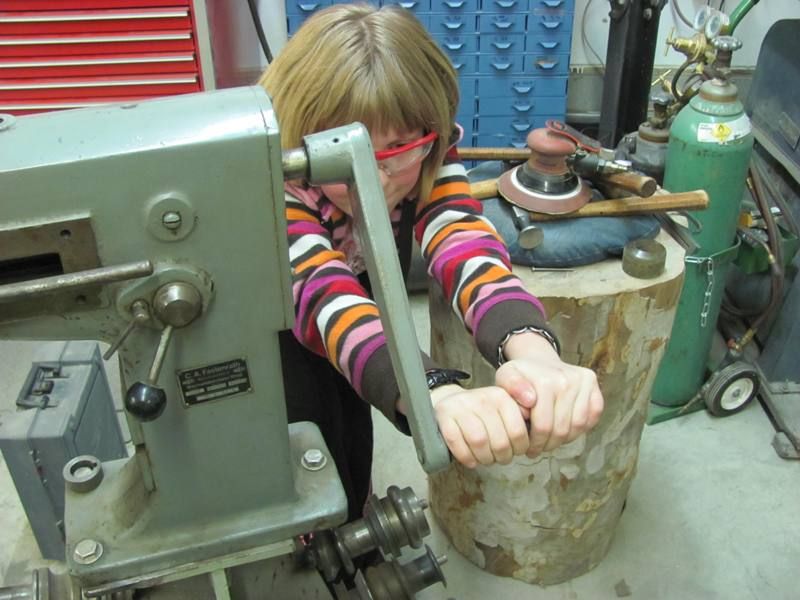
I had some help in the shop this evening, so in addition to having the powered option on the bead roller this evening, given the diameter of the gauge bezel, I was able to show her real world application of Pi X D....
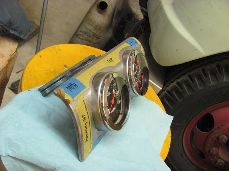
Just to test fit, here's the gauge with bracket, and the ring placed over both....
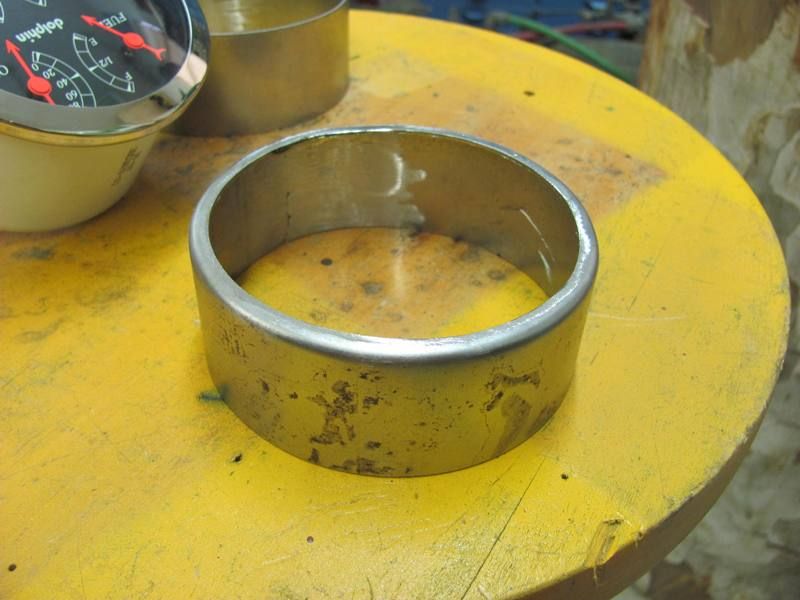
Both rings formed, tomorrow we'll get them welded up and tip some flanges for the bracket to push against...
Comment
-
Nice stuff going on in this topic!
If I were to make dashpots like those I'd probably be eating soup that evening and use the can which it came in :o)
I got myself a beadroller last year mainly for a future project which involves a lot of floorboard making, but I really like to start using that thing upfront to get some 'rol-time'.Last edited by BigBlockMopar; March 3, 2013, 02:47 AM.Comment
-
Soup cans....just think of all the work that would have saved me!
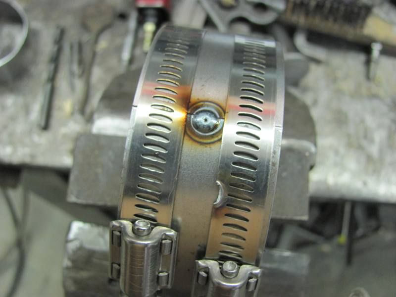
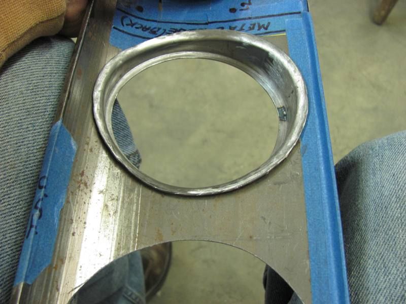
Worked on the gauge panel again today, got the rings welded up...
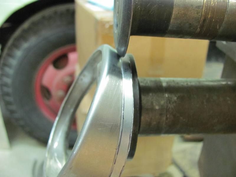
Then to tip a flange to hold the gauge in place, used these in the bead roller....
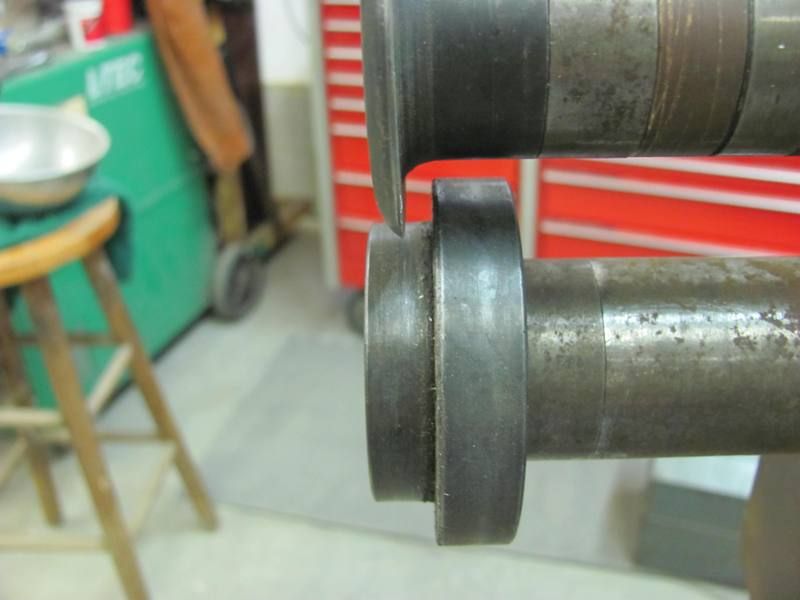
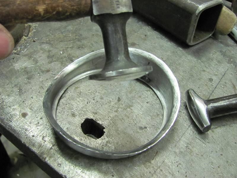
Applied a bit of pressure and started tipping the ring gradually as we went....
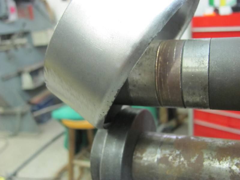
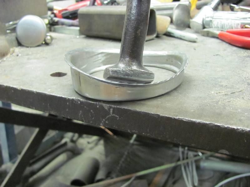
After getting the initial flange tipped to almost 45 degrees, the body hammer was used to get the flange to 90.
Fitted, and shown with the gauge's mouting bracket in place.....
Now to fit the rings to the panel....
....and fine tuned with a drum sander.. A view in the panel....
Rather than weld around the perimeter of the hole, which will surely warp things up nicely, I'll tip a flange on the underside of the rings and spot weld to the panel.Comment
-
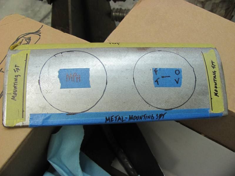
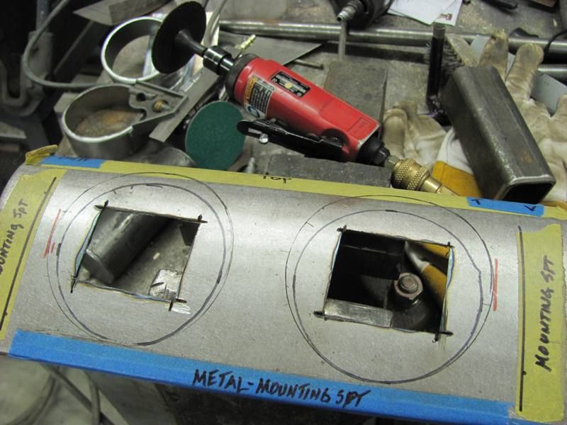
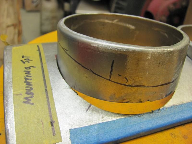
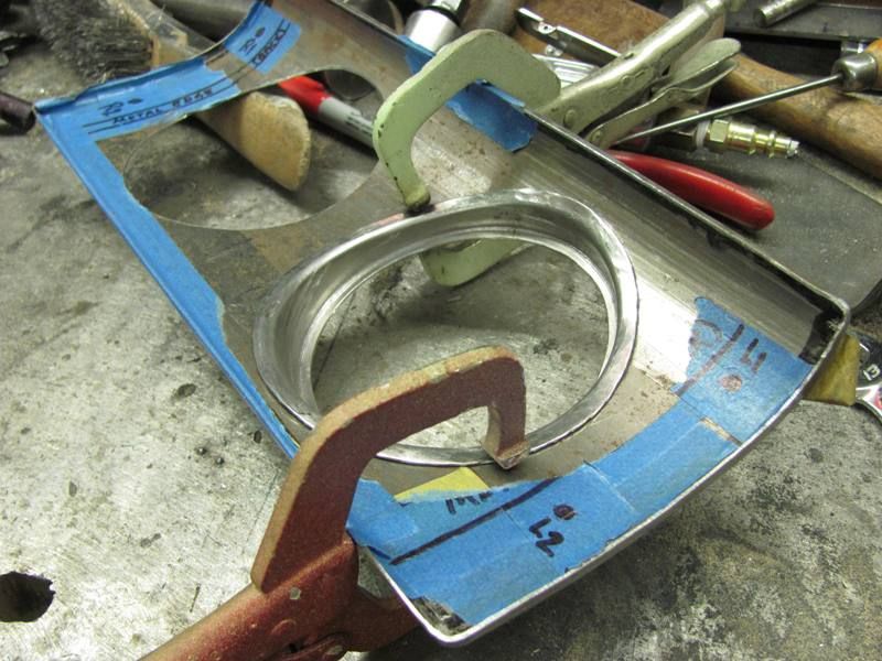
Here's the tipping process for the rear ring flange. Before marking anything, the panel and both rings were pushed flat to the "table" surface. Then alignment marks added to keep us in the right location....
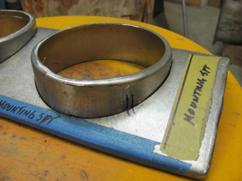
Marked along the surface of the panel against both rings..
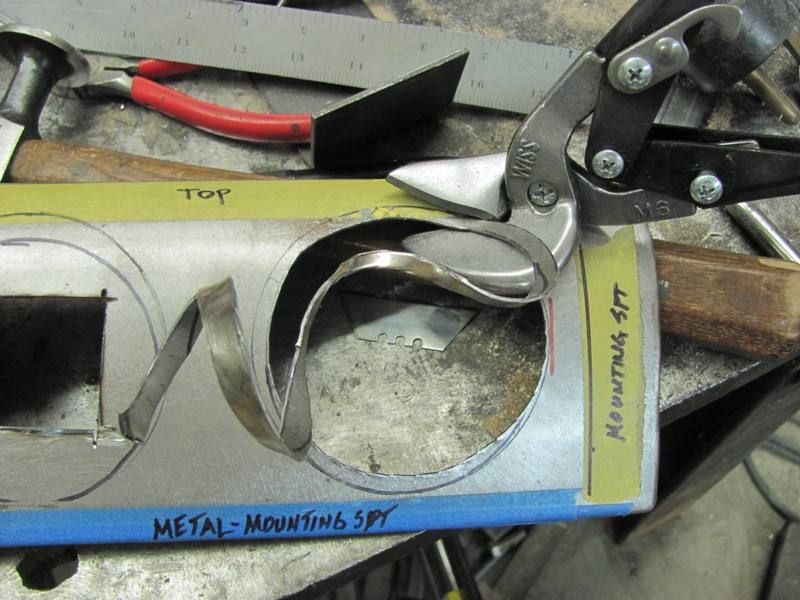
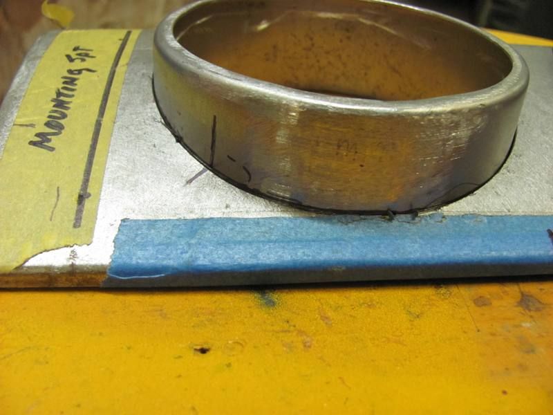
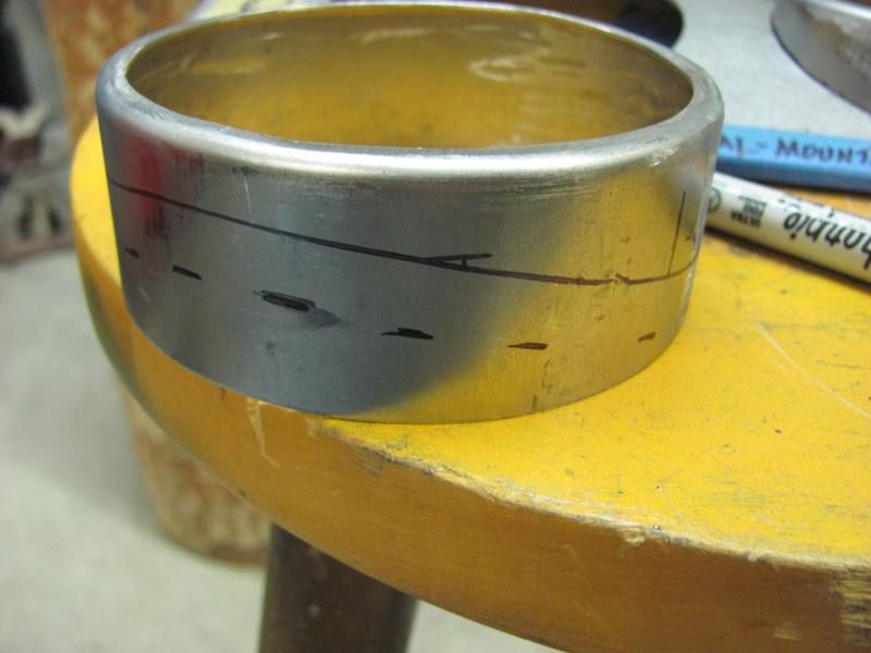
Did an offset line 3/8" away and trimmed. This looked too wide to tip, so I went back and marked again at 3/16".
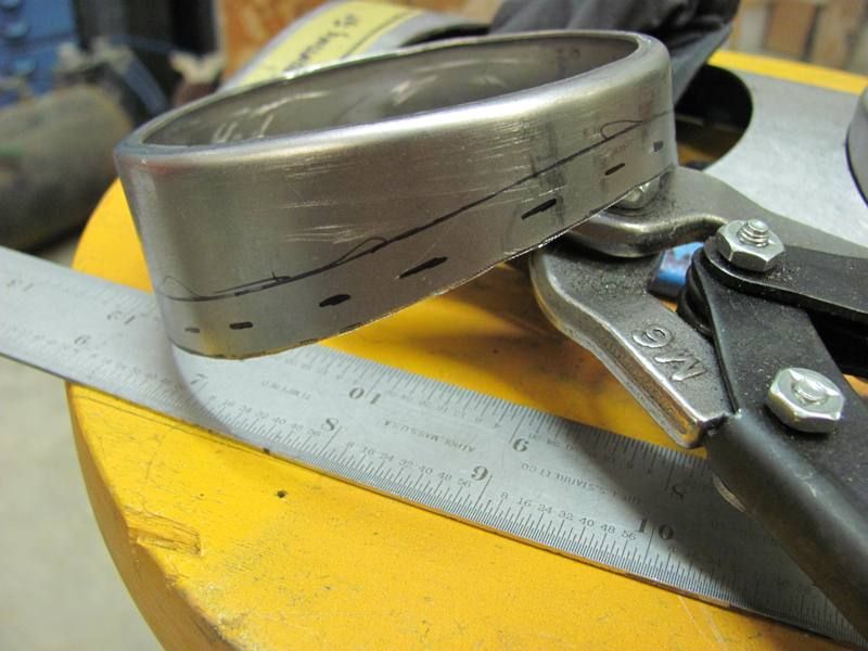
.....and trimmed again to the 3/16 mark. Changed to a different lower die for tipping this time.... made a complete revolution to "mark" the bend line and then started tipping...
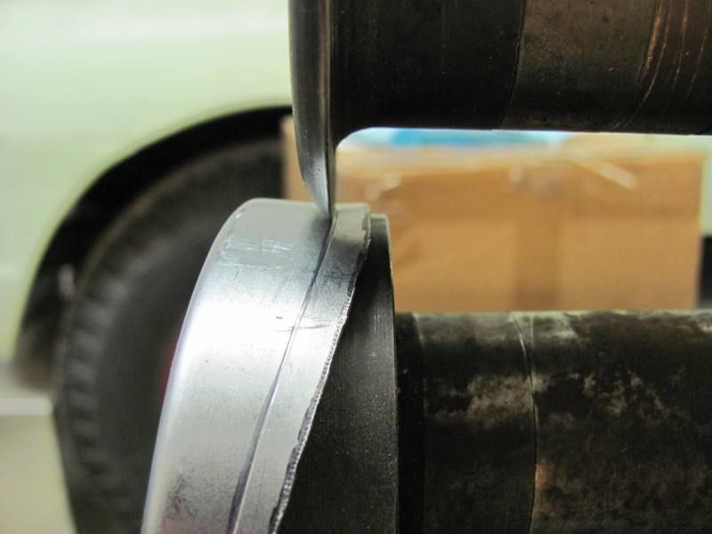
Again went to about a 45 degree tip, placed the ring in the panel to see what needed more tipping....
Tipping along a wavy line does pose some "pulling" issues, so I did have some planishing/stretching to do in some areas. It's real close, but I have some tweaking left to do, and then I'll tackle the second one.Comment
-
holy father of metalworking awesomeness....I want you and Big Dad to adopt me...I am house trained, and can turn a wrench. I can eat scraps and 19 years of military service has made me quite good with a mop and broom.If you can leave two black stripes from the exit of one corner to the braking zone of the next, you have enough horsepower. - Mark DonohueComment


Comment