


So we’ve been off our normal schedule with Project Violent Valiant updates and consider this our effort to get back on the horse and keep you apprised of the developments of this awesome build. Kevin Tully at Hot Rod Chassis and Cycle in Illinois has been busting his hump on the car between the roll cage and chassis work he has done so far. Today we’re going to look at the front suspension which will be helping this gnarly little A-Body turn corners harder than anyone expects it to!
Utilizing his own skills and design acumen to come up with the exact configuration he wanted to use and then employing components from RideTech, this little car should really be something else on both the road course and the cone course once it is complete. In talking with Kevin, if he can keep on his own personal schedule, he’d like to see the car on the ground and burning tires by the end of July. We’d like to see that as well! This work on the front suspension is a big step in that direction and Kevin also told us that the engine is moving ever closer toward fire up time. If you remember correctly, the engine is a 500+ ci aluminum block Chrysler wedge engine. OOGA BOOGA! But we’re getting ahead of ourselves. Let’s take a look at the progress that Kevin has made and why he’s doing what he is doing with the Valiant!
We should also note that this front suspension wasn’t just something that Kevin woke up from a dream and sketched out one morning. The whole thing is computer designed using some neat CAD software that is specifically intended for use in the creation of road racing suspensions. By using this software, Kevin can get optimal performance out of the car and he knows that if he does his fabrication end of the job correctly, a good working car is the payoff. Now, the beauty of this is that you can be the best CAD guy in the world and design some really trick stuff but unless you can actually make it come to life, you’ve got a whole bunch of nothing. Like they say, the proof is in the pudding. In this case the proof will be in the skidpad!

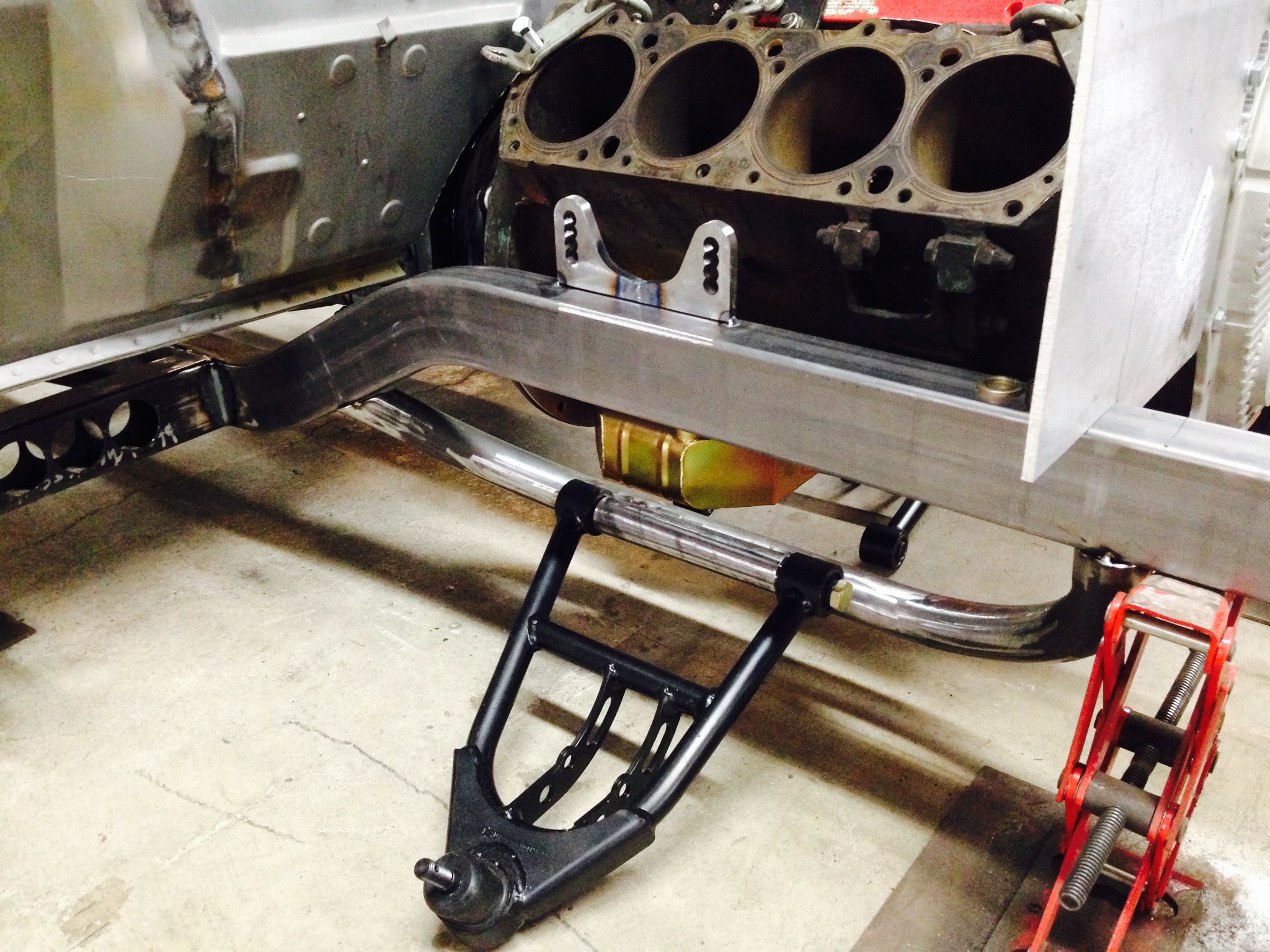
Here’s where we last left you. The front frame rails with the 275 width front tires mocked up into position. At this point, Kevin went into fabricator mode. The first thing he needed to do was to figure out exactly where the engine would lie.

While it may seem simple enough to just set a 413 block in there and take some measurements, this is one of the most critical pieces of the project. Figuring out exactly where the engine will set defines where headers go and basically plots the course of the rest of the build.

Like every other part of the build, making sure that everything is true and level is essential to the success of the end product.

The block in the car is a “stunt block” and is not the aluminum Indy piece that will ultimately be serving as the basis for the engine. By mocking the heads, oil pan, and intake on it, Kevin can judge if his placement is right before making permanent alterations to the car that would be a pain to undo.

Flatter than Kansas, baby!

With the engine where he wanted it, Kevin turned his attention to the front suspension. He made the brackets to mount the upper RideTech “Strong Arm” and then made the cool tubular mount for the lower RideTech “Strong Arm”. He made the brackets as well and we’ll show you those in a little bit. The tubular lower mount is strong and light…two elements that have been stressed about this project.
Another look at the tubular lower mount for the control arm. These Strong Arms have a specific application for a Mustang II but they fit the dimensions that Kevin needed.
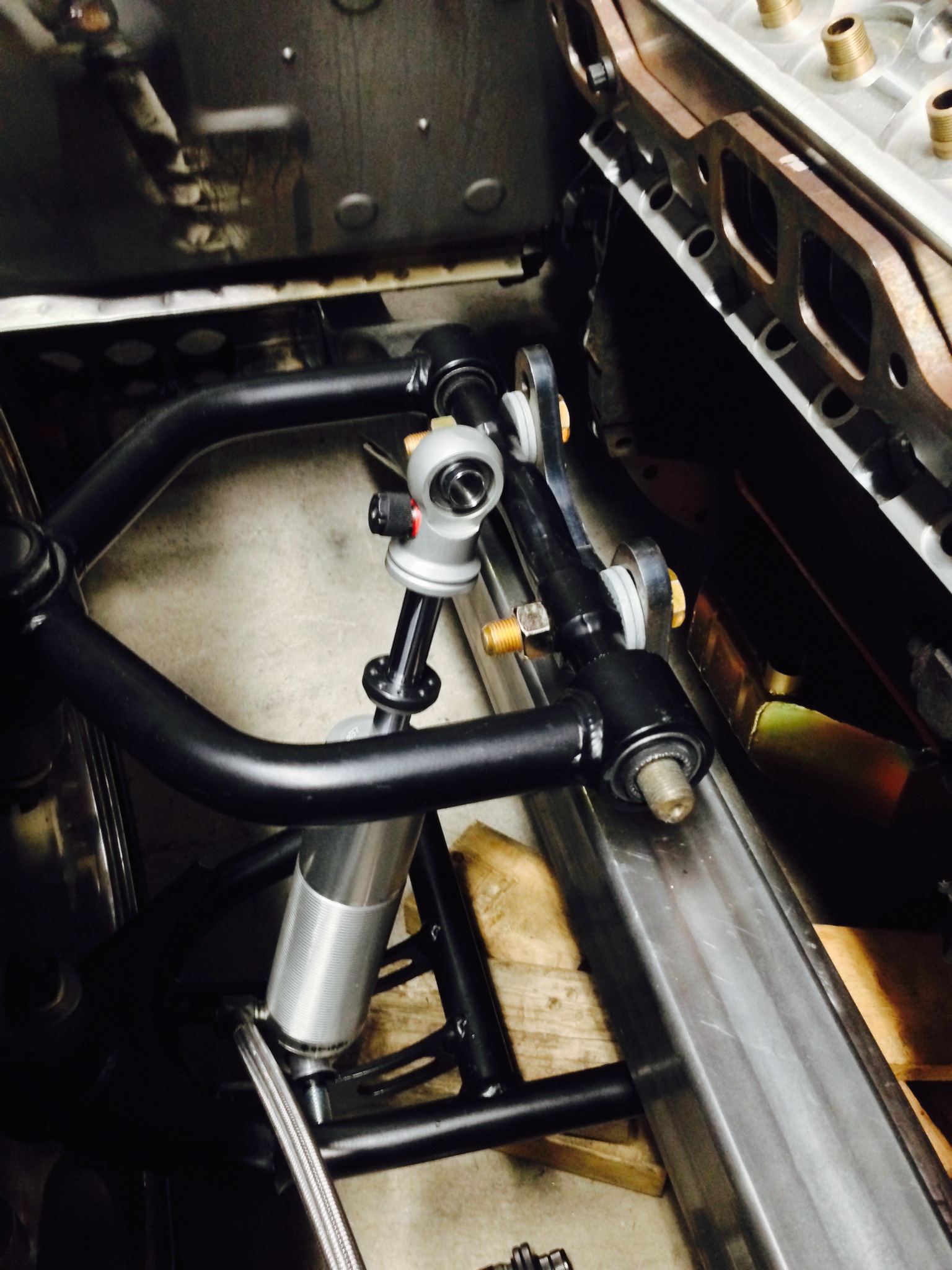
Here’s a look at the triple adjustable “Track Quality” RideTech shocks that will make up the brains of the front suspension. In this photo, Kevin has a shock laid in to start measuring and mocking up the upper shock mount.
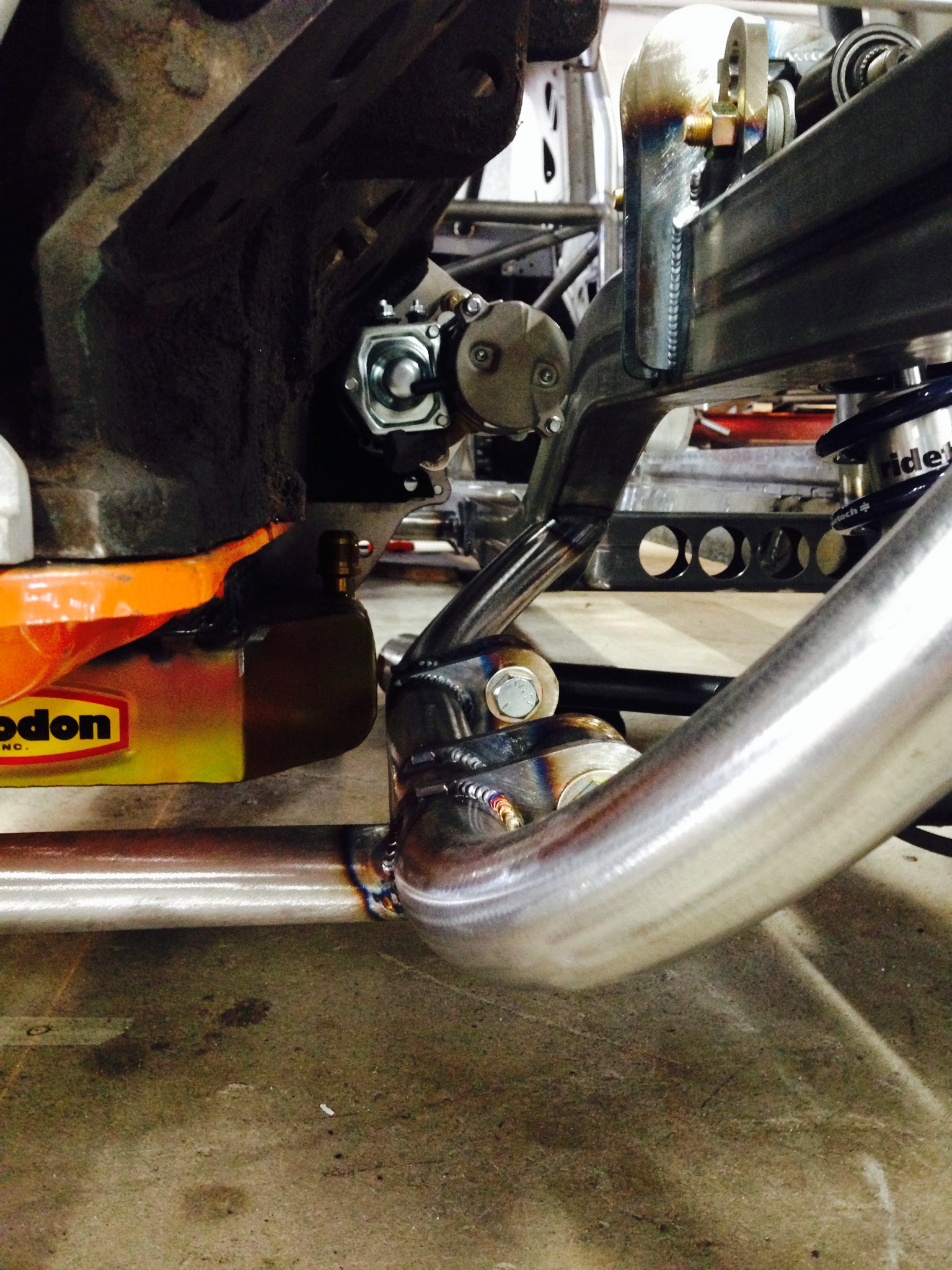
Here’s a more wide open look at the lower arm and the cool upper control arm mount that Tully fabricated. That upper mount will hang onto the RideTech Strong Arm upper control arm for dear life!
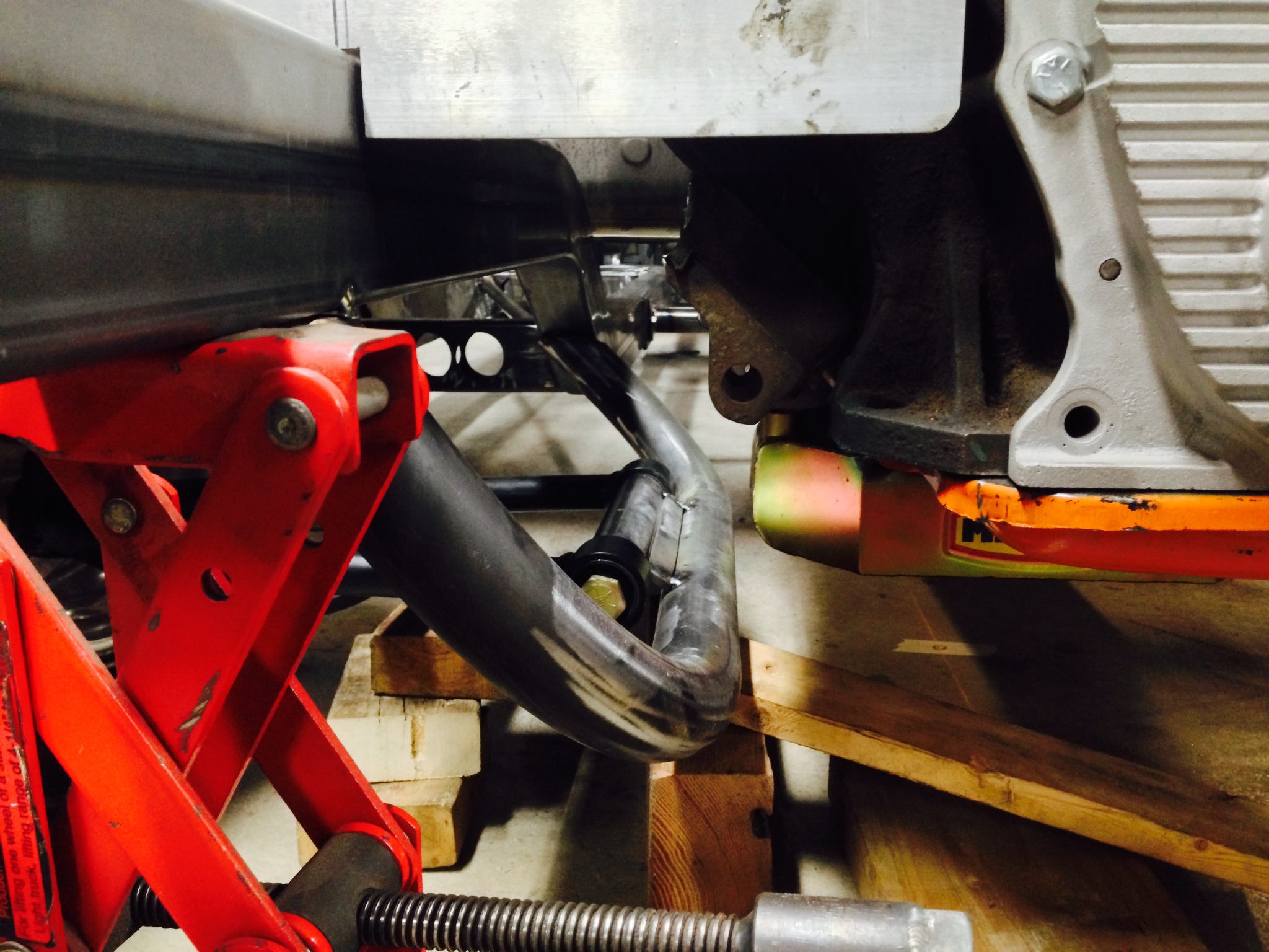
Two things to peep at here. We have the mounting tabs that Kevin made for the lower control arms and the modified Milodon oil pan that Kevin cut and welded to fit his specific and unique needs on the Valiant. You may be asking, “What’s the ride height of this thing?” The answer is that there will be no point on the car closer than six inches to the ground when on the rolling stock.
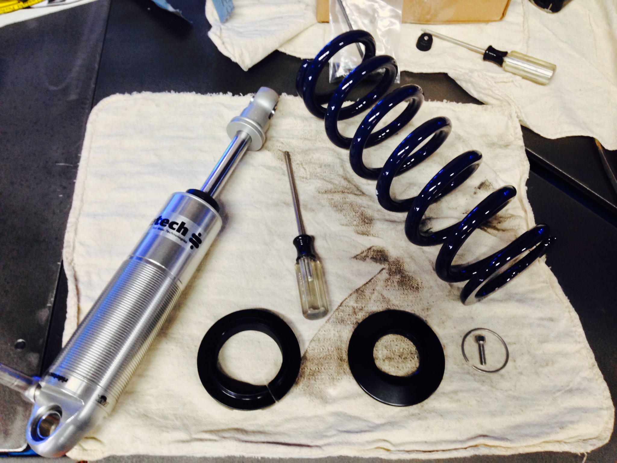
Here’s another look at the RideTech “track quality” triple adjustable shock and the spring that Kevin will be using on it to start with. Once the car is done and on the track, chassis tuning will be critical to make sure it works as good as it can and should.

We’re jumping the gun a little here but dang this looks good! With a combo of raw fabrication skills and the use of some really good parts this little car should really be able to freak some people out at events this summer.

Like we said, no part of the car is lower than 6-inches to the ground which will make this a 100% care free driver. No worries about speed bumps or raised manhole covers, etc.
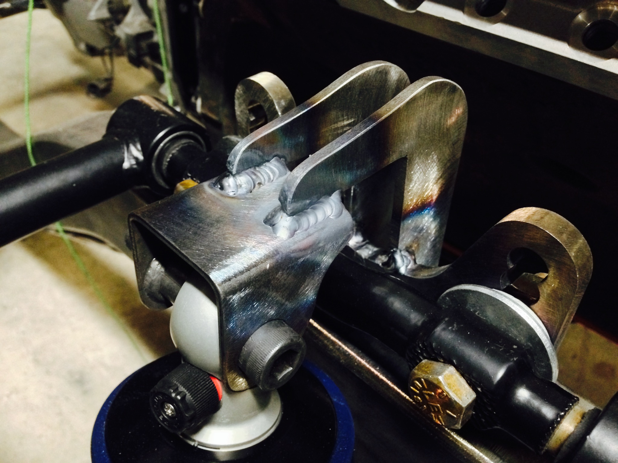
The upper shock mounts are things of industrial strangth beauty. Note that they are tied directly into the frame to promote stiffness and rigidity. Kevin went with this design because with the stiff spring he anticipates using on the car, these mounts will be under a lot of stress. Strength in this area will be key because a shock mount failure on the track could be catastrophic.

Another look at the upper mount.

Here’s a clearer picture of the front shock mount with the triangulated tie ins to the chassis.

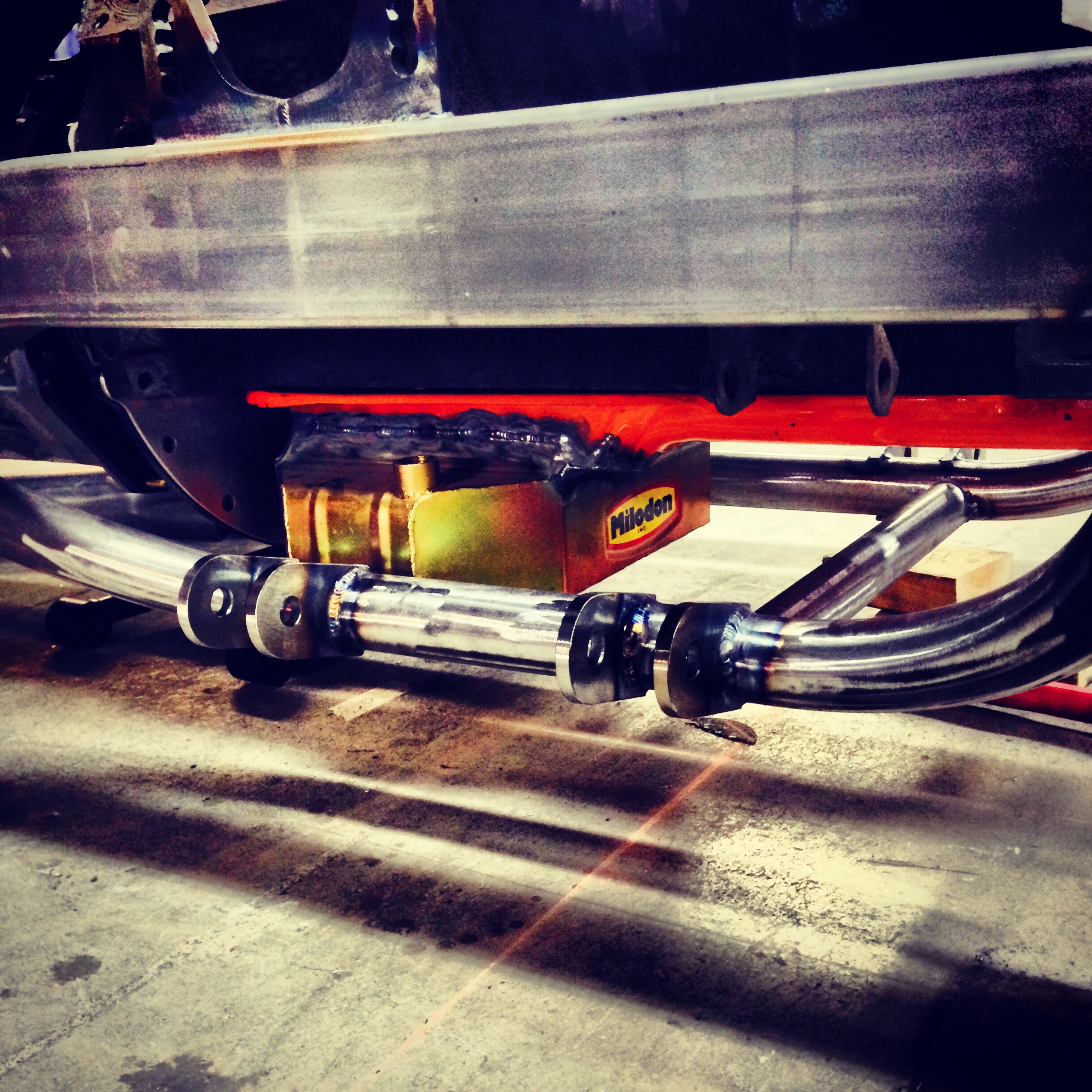
Kevin added this bar to both stiffen the front and and to mount the steering rack on. He has since tweaked it a little but we like this photo because it gives you a good look of the business side of the front end. Note how the oil pan is level with the chassis. No bashing that puppy!

Another good look at the tubing and fabrication that has gone into this part of the car thus far. Far lighter and stiffer than stock!

Too bad it is all going to be hidden by the body and the only way we’ll see it this clean again is if we strap a GoPro under it before the first lap at the track. A thing of beauty for sure.
We’ll be talking headers in a later update but here’s the room that Kevin has to work with on the driver’s side of the car. He’s going to build 100% legit equal length pipes for this car and we can’t wait to see it. Next week we’ll be updating you on the progress being made on the body end of the car. Believe it or not…it is getting prepped for painting!
CLICK HERE TO SEE EVERY UPDATE ON THE VIOLENT VALIANT SO FAR — PROGRESS!


I don’t think I’ve ever seen a street a-arm suspension with zero anti-dive, but hey that’s a choice. I would strongly suggest anchoring a dial indicator off the frame a little back from the a-arm then taking a reading off the upper shock bolt as the chassis is loaded and unloaded to simulate a couple of g’s for a check on that mounting scheme, as stated it’s an important area with other options still open on design.
As before, nice fab work, this is going to be a gorgeous car..
Loren, Where in the article does it say that the car has zero anti-dive? There’s plenty of anti-dive designed in to the front suspension, along with roll center height. All done on a CAD program, and then transferred to the car. Not to mention the upper mounts allow for adjustment of roll center height, caster, and anti-dive.
The pics not the article say there’s no anti-dive, essentially the axis through the lower and upper a-arm mounts appear parallel or close. I do see the adjustability there which is going to be handy dialing that in with those tires.
Stiff front suspensions don’t have to have anti-dive, it’s done because it’s easy as much as anything. A little is helpful, lots gets you skittishness hard braking on a rough surface, so it’s not a big deal either way.
If you show the world your designs, your gonna get the annoying critics as well as the admirers. 😉
The anti-dive is built in. The entire front suspension was plotted on a CAD program that allows you to move the suspension though it’s range of motion. When final assembled, the upper control arm will be bolted in at the #1 rear and #2 front holes in the bracket. The upper and lower ball joints are also not in line vertically. The upper is to the rear of the lower. Photos and mock up don’t mean that’s how the car is final assembled.
As a matter of fact, if you look at the photo of the shock mocked in with no upper mount, you’ll notice that the upper arm is bolted in as described.
Great work so far! I really dig the upper control arm mount, such a novel idea that’s been implemented on other suspension mounts (panhard bar, lower rear shock mounts, etc) but I haven’t seen it done for UCA’s before. Very cool!
I will side with Loren though. The upper shock mount looks a bit suspect. Certainly in comparison to the rest of the work done. Upon compression, the U tab will be cantilevered about the outermost point of the L bracket. The moment induced will put your weld into an awkward tension loading….and there might not be enough weld leg there to resist it. If I may suggest; the L brackets look great, keep that design. Extend them though and have your upper shock bolt pass through them. No need for a second tab welded on. Gusset the two L brackets with sheet (dimple die some holes to add lightness) and it will be structurally sound and aesthetically pleasing. Just a suggestion though! I could model something up if you’re interested.
Keep up the good work…and the updates!!!
Rye,
I think I see what you guys are talking about. If I may suggest, wait, you aren’t seeing the entire structure yet. Remember, this is just one update. There is a ton more fabrication work to be done on the front of the car. And you guys aren’t seeing the REST of the shock mount just yet. Next update will have photos of the front half of the cage, and include the REST of the shock mount. Deal?
Deal! Looking forward to it man!
I enjoy seeing the work in progress on this car, the fabrication work is incredible.
Nice stuff, I have a MGB V8 going together in NorCal with CAChassisworks components and seeing your pictures and how close mine is to yours (a little more low buck, QA1 coilovers, a little less adjustability), Mine is just a street car, less H.P., less weight (about 2300 lbs.) makes me think my chassis guy (Bill Galli) has a good plan. Can not wait to see your finished product, looks awesome.
Still my favorite BS project rolling!
I’ve been checking the site daily and holding my breath, hoping for another V.V. project update!
Great work, Kevin!