


We’re back with another update on Project Violent Valiant the unique pro touring destroyer being built by Hot Rod Chassis and Cycle‘s Kevin Tully at the Skunkworks in Illinois. In case you have been in prison or otherwise away from the computer for the last several months, we have been following this build on a near weekly basis as a stock Valiant was driven into the shop, blown apart, and is now being built into a Chrysler powered, full tilt, corner burning pro touring car literally from the ground up. In this installment, we’ll see Tully installing the front frame rails that he fabricated for the car. We’re getting close to actually seeing this thing down on four wheels (maybe there’s even a teaser shot of that at the end of this update!) but there’s still a long way to go to complete the car and get it burning tires yet. We’re still neck deep in the fabrication portion of the program and it sure is fun to watch this thing get filled up with round and square tubing from a metal master like Kevin. Now….onto the update!
[divider]
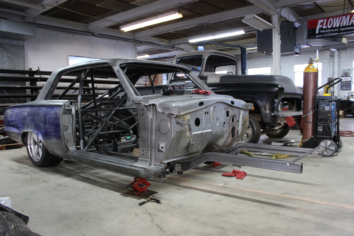
Not to blow a “surprise” but here’s the 2×3 .120 wall rectangle tube rails as they looked after being installed into the car. Kevin reports that this isn’t the most complicated of processes, but that measurements and precision are paramount. These will serve as the foundation for the car’s suspension so accuracy is critical.
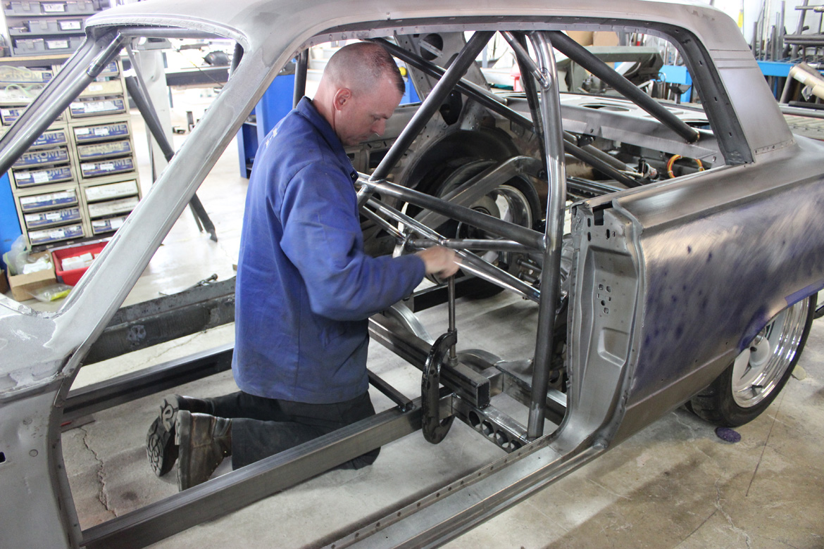
The frame rails are 28″ apart which is pretty narrow but this is a little car, so it all makes some sense. Kevin didn’t just pull that number out of the air, it was achieved by mocking up the front end with the clip positioned as it will be on the completed car. Kevin reports that it is important to take the time to do the mock up with the spindle and brake rotor, among other components to make sure everything is going to fit. After seeing what he needed, 28″ was the number and he went for it.

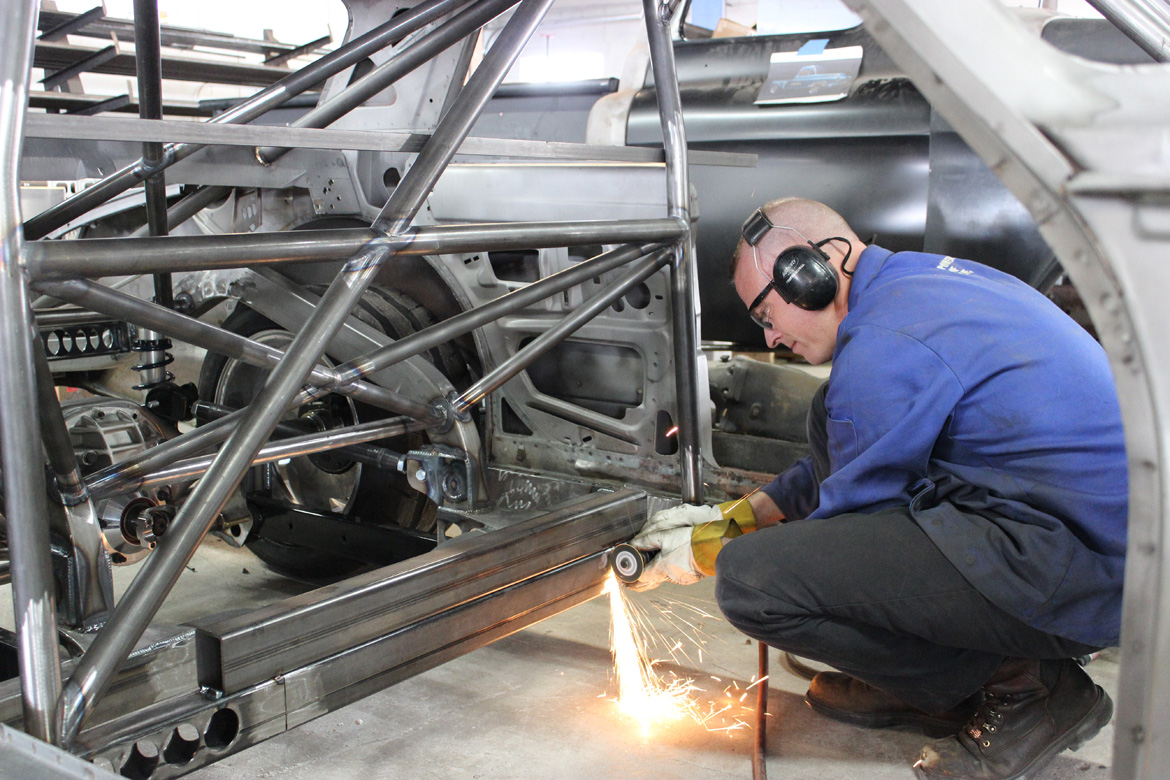
After bending up the rails, laying them out, and affixing them together with three small cross members on a work table, Kevin was ready to install them into the car as their own subassembly. Measuring in from each side, Kevin marked the center crossmember of the car and began cutting the center out of it. The front frame rails will pass through this opening and tie into the rear frame which was completed in an earlier update. The piece on the top that you see in this photo is welded in four spots and will keep the car true and straight when the bottom is removed. Kevin starts the cut from the top with a Porta-Band saw, welds the sistered piece in, and then finished the lower cuts with a wheel as you see here.
Kevin said that he had a total of about 4-hours in the actual installation of the rails. Rushing this type of work can lead to disaster because the success and performance of the car are literally dependent on things being straight, true, and strong.

So here’s what we’re left with with the center out of that crossmember. You can see the new frame rails lying below it on the floor. Kevin told us that if you did your job right these should be a nice tight fit up into that space. We’re happy to report that they were.

These man-sized C-clamps were used to hold everything in place so Kevin could finish weld the rails in.
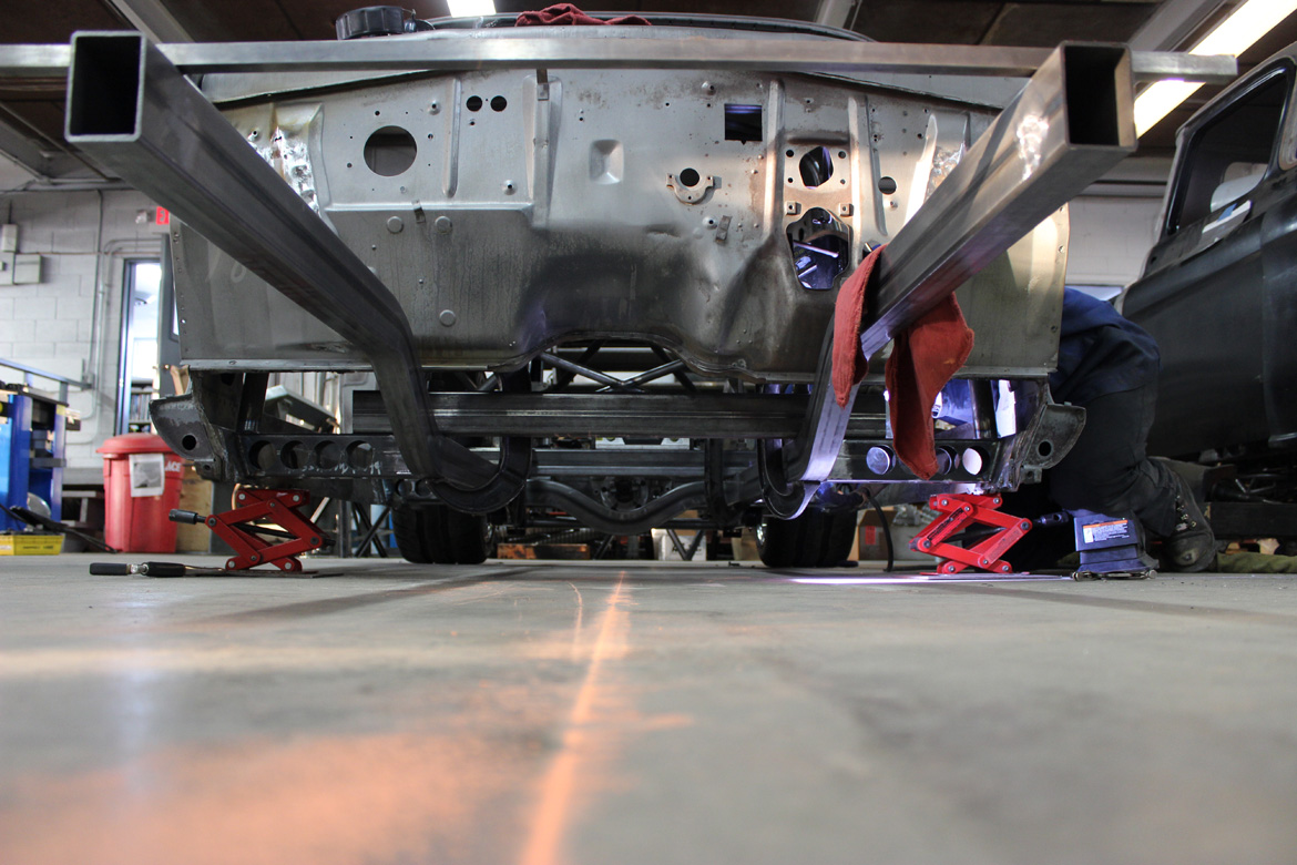
Here you can get an idea of where the front frame ties into the rear frame of the car.

Once things were clamped into place, the next critical step was to make sure that everything was still happy, square, and where it should be. Here we can see Kevin using the plumb bob.

So with all the measuring and figuring done, Kevin was ready to make the commitment and finish weld the frame assembly in. With 3″ weld beads in what Kevin told us were 12 locations, strength and stiffness aren’t going to be concerns.
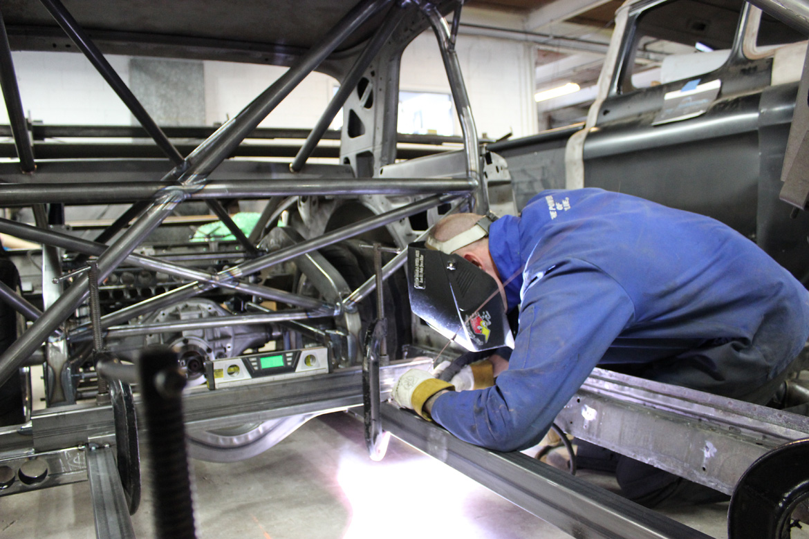
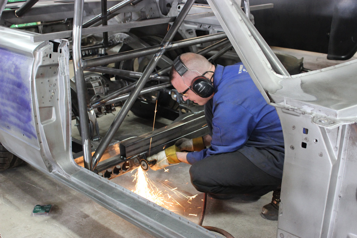
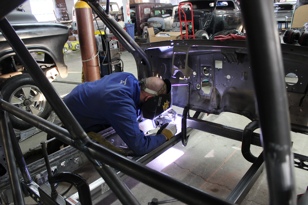
Kevin had to wedge himself into some tight spots to burn all this steel together.

With the rear welded in, Kevin moved to the front crossmember and made more puddles of molten steel.
We need some of those clamps. Those babies could support a bridge!
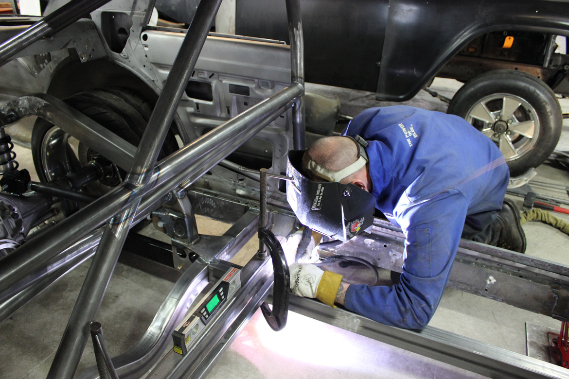
Note the ever present digital level. Kevin said that he was constantly checking it to make sure everything was square and happy.
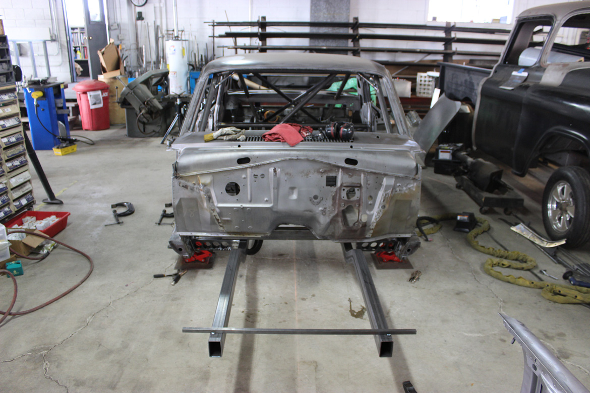
While it may just look like a couple of rectangular tubes hanging out in the breeze, the fact is that those frame rails mark an important step forward for the project. We now will start to see the front suspension come together and lots of other fun stuff. This is getting good!

Oh! And about that teaser photo we promised you of next week’s update…
CLICK HERE TO SEE ALL OF THE VIOLENT VALIANT UPDATES FROM THE BEGINNING UNTIL NOW


Could someone explain why the only tubes to get “swiss cheesed” are the ones
that the roll cage mounts to? Beautiful work BTW.
Yep, maybe fill those last couple in again, gotta be flexible on stuff like that. Whatever the design choices, there certainly is some careful craftsmanship going on there.
Impalasam, if you look at where the main hoop is welded in, there is no lightening hole under the anchor point. And the cross member is welded to a 1/4″ anchor plate that covers 36 sq in. of the rocker. On top of that, a new floor will be plug welded to the rocker and the cross member. There is also additional tubing that will go below the floor section that you’ll see in the next installment. Not to mention the cage structure just behind the main hoop (7&8 bars) that anchor the main hoop from the back bar to the top of the rear frame rails about 14″ aft of the main hoop. If you have additional questions, please feel free to ask. I’m more than happy to answer. Kevin Tully
Curious what you are using for front suspension pieces? Working on c4 corvette suspension in a falcon. Just curious…
Torsion bars, please
Ridetech Strong arms, Flaming River Road Race Rack, and Ridetech TQ Triple Adjustable Shocks, MII Spindles and Raybestos 2010 Dodge Charger Police Pursuit Brakes.
Coils front and rear, 9″ Ford….on a Mopar. What’s next…a Mustang R & P ? Shoulda built a Nova.
Fail
With an all aluminum, stroked 440 with a Hilborn Stack Injector and MoPar Super Stock seats? That would have looked pretty silly in a Nova.
440 Roadrunner, I’m sure that Kevin appreciates comments and creative suggestions but when you build a car of this magnitude you use the components that you feel is the best fit for the build. Coils are the choice for most builders and you don’t get any better than “Ridetech” as well as the 9″ Ford type “Moser”. I know that Kevin is building a Mopar and you being a Mopar fan (440Roadrunner) you would rather see a Dana 60 or 8 3/4 Chrysler. For this application the Dana weighs a ton and the 9″ is considered to be stronger than the 8 3/4. As for the Mustang R/P, I don’t think I would use one out of a Mustang but many companies make a “Mustang Type” that is far superior to the “Ford Mustang”. “Shoulda built a Nova”? WHY! Having had the pleasure to meet and talk in depth with Kevin several years ago at the Hotrod Restoration Show here in Indy, he is one of the most knowledgeable and “pleasant” car builders I have had the opportunity to meet. Finally, if you are 440roadrunner, why build a Nova”? Really! Keep up the great work Kevin I’m anxious to see the completed project and I’m still working on my ’57 Ford Sedan Delivery, “Gasser”. “Turbos Don’t Suck”!
Thanks Terry. I didn’t comment on the “Mustang R&P.” We’re actually using a Flaming River Road Race Rack. As most rack and pinions are all the same design, just different widths, mounting locations, and thread size, I’m not really sure anyone uses OEM racks any more. The rack we’re using has a larger valve body, larger rack gear, is totally customizable for width, mounting points (pillow block type), front or rear stear, valve reaction time, input/output hose location, and arm length. It’s a race car. And as everyone knows, race cars are a hodge podge of aftermarket parts. And yes, some are OEM inspired. The Ford 9″ for example. I’m not sure everyone knows, but most every NASCAR on the track runs a C&R Racing 9″ center section. Chevy, Dodge, Ford, Toyota. Sorry guys, power plant and body are often all that’s left from the OEM when building a race car. I used control arms that are, yes, intended for a Ford. But they are aftermarket, and were the correct length for the application. I’d also like room for my headers and collectors. And Torsion bars just don’t give you that. Nor are they available in enough spring rates to allow me to tune the chassis for turns that will more than likely be several G’s on the compression of the spring.
Will you be keeping the existing firewall or hand fabricating a new one?
Fabricating a new one. The original heater is GIANT, and weighs about 40 lbs. It would have been in the way of the 11&12 bars for the forward half of the cage. We’ll use a Vintage Air heater instead. And then filling all the holes in the existing one for the heater, clutch assembly, original pedals, wiring, throttle, etc. would take four times as long as just making a new one. And we were able to push the motor back another 1/2″ as well.
This has to be one of my favorite projects in all of motoring.
Keep up the great work HRC! Violent Valiant updates are always something to look forward to!