Announcement

Collapse
No announcement yet.

Autometer Gauge Disassembly

Collapse
X
 
  • Filter
  • Time
  • Show
Clear All
new posts

  • Autometer Gauge Disassembly

    Howdy,

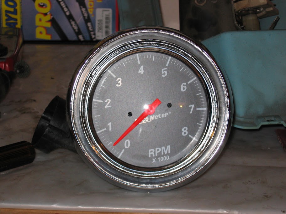
    have any of ya'll taken an Autometer gauge apart to use the movement for a custom gauge of your own or to otherwise service the guts?

    Thanks,
    Central TEXAS Sleeper
    USAF Physicist

    ROA# 9790

  • #2
    Re: Autometer Gauge Disassembly

    Nope ,just chicken and, well hey ,they make a better looking gage than I would any ways.

    Comment


    • #3
      Re: Autometer Gauge Disassembly

      can i help


      <<<<<<<<<<<

      lol neat idea get to tearing apart take pics and let us know how it works

      Comment


      • #4
        Re: Autometer Gauge Disassembly

        If I can get the case off of it I could attach it to the metal can of the original clock and put that in the clock position that I'm using for a boost gauge instead of getting the clock bezel opened up a slight bit and then pressing it over the stock autometer bezel then turning down the clamp to hold it in.
        Central TEXAS Sleeper
        USAF Physicist

        ROA# 9790

        Comment


        • #5
          Re: Autometer Gauge Disassembly

          the trim ring on auto meters hold the glass to the case get that off and what looks like holds stuff in on back and guts come out don't know if needle will come off or notmight f up gauge pulling it off be carefull

          Comment


          • #6
            Re: Autometer Gauge Disassembly

            Maybe these people can help..

            Comment


            • #7
              Re: Autometer Gauge Disassembly

              It's just a matter of having the balls to cut off the front retaining ring, the rest should be easy.
              My fabulous web page

              "If it don't go, chrome it!" --Stroker McGurk

              Comment


              • #8
                Re: Autometer Gauge Disassembly

                drat, I was hoping I could somehow pry the plastic cup off the back of the ring and get it out that way.
                Central TEXAS Sleeper
                USAF Physicist

                ROA# 9790

                Comment


                • #9
                  Re: Autometer Gauge Disassembly

                  oh, they have plastic? Huh...the older ones I have are all metal. I guess I'm really out of the loop!
                  My fabulous web page

                  "If it don't go, chrome it!" --Stroker McGurk

                  Comment


                  • #10
                    Re: Autometer Gauge Disassembly

                    the ring is crimped on like a bottle cap sorta pretty much gotta f it up to get it apart


                    this guy might be able to help LOL

                    Comment


                    • #11
                      Re: Autometer Gauge Disassembly

                      Good luck with that project, take pictures for the rest of us.

                      Comment


                      • #12
                        Re: Autometer Gauge Disassembly

                        You could try doing what I did, I found an old gauge at a swap meet that matched mine for $3 and did some "exploratory surgery" on it to see how it came apart. I figured if I ruined it, I was only out $3 instead of ruining my good one's.
                        Just groovin' to my own tune.

                        Comment


                        • #13
                          Re: Autometer Gauge Disassembly

                          I was kinda wondering about the same thing. Thought it would be cool to mount some higher-quality instruments behind the factory lenses.

                          Comment


                          • #14
                            Re: Autometer Gauge Disassembly

                            Let us begin, no this isn't the boost gauge, that is going to require modifying something pretty heavily so I'm still weighing my options. Check this out though with what I did with my other autometer gauge, a 5in Classic Chrome in dash Tach.
                            Here is the best picture I have of the dash setup before I modified it. I forgot to take one of the unit before I took it apart.

                            The pods are a 5in speedo on the left and a 5in "quad gauge" that is really just a gas gauge and the oil pressure, brake, hot, cold, and Amp idiot lights. The little one in the middle is a 2in clock.

                            Here is what it looks like disassembled with the stuff laid out in front of it.

                            I've taken the labels and backing plate out of the bezel and the small one is the clock that will be getting the boost gauge.

                            Here is what I'm putting in the holes.


                            Here is a comparison shot of the rings that hold the stock lenses into the backs of the bezels.

                            The top one has been pie cut so I can open the opening up to the 4.6in needed for the autometer tach before I gently bent them with a pair of plyers that I wrapped the jaws in tape.

                            This is the whole stock bezel held onto the tach which has been pushed through the mounting ring after I bent the pie cuts clear. It doesn't sit flush but the mountings to hold it to the cluster are in the heavy metal ring, not in the ring.


                            Here is the result of me hogging out the light guide tubes inside the gauge so that the tach will fit down inside of it.

                            I did this with a fiber reinforced cutoff wheel on my dremel and a plastic/light metal high speed cutter to clean it up and grind away stuff. I had to modify the bottom hold down tab because the boss interfered with the tach so I cut the eyelet off then drilled a hole in the wall of the cup with it clamped in place then used the whitness mark to place drill a screw hole in the tab and mounted it to the wall.

                            Here's the final product.

                            I know the tach isn't straight but this is just the first mounting as I have to wire it up later so I'll put updates on this project as I put the boost gauge together. I'm about 95% sure that I'm going to cut the bezel off of the gauge pull it out of the plastic can then put the mechanism in the clock metal can. If I get lucky I can route the wires for the illumination and the vacuum tube out the stock wiring ports in the back of the gauge.
                            Out of curiosity, do they make little plugs that are shaped like an old wedge pack bulb so I don't have to cut the clock illumination wire to get power to the autometer gauge light?

                            Hope ya'll enjoyed it
                            P.S. This is my first time using Google Picasa photohosting. Let me know if its not working for ya'll, I had to right click and show picture on some of them.
                            Central TEXAS Sleeper
                            USAF Physicist

                            ROA# 9790

                            Comment


                            • #15
                              Re: Autometer Gauge Disassembly

                              I´m only seeing one picture, the comparison shot of the rings .

                              Comment

                              Working...
                              X