Announcement

Collapse
No announcement yet.

3 steps forward, 2 steps back

Collapse
X
 
  • Filter
  • Time
  • Show
Clear All
new posts

  • 3 steps forward, 2 steps back

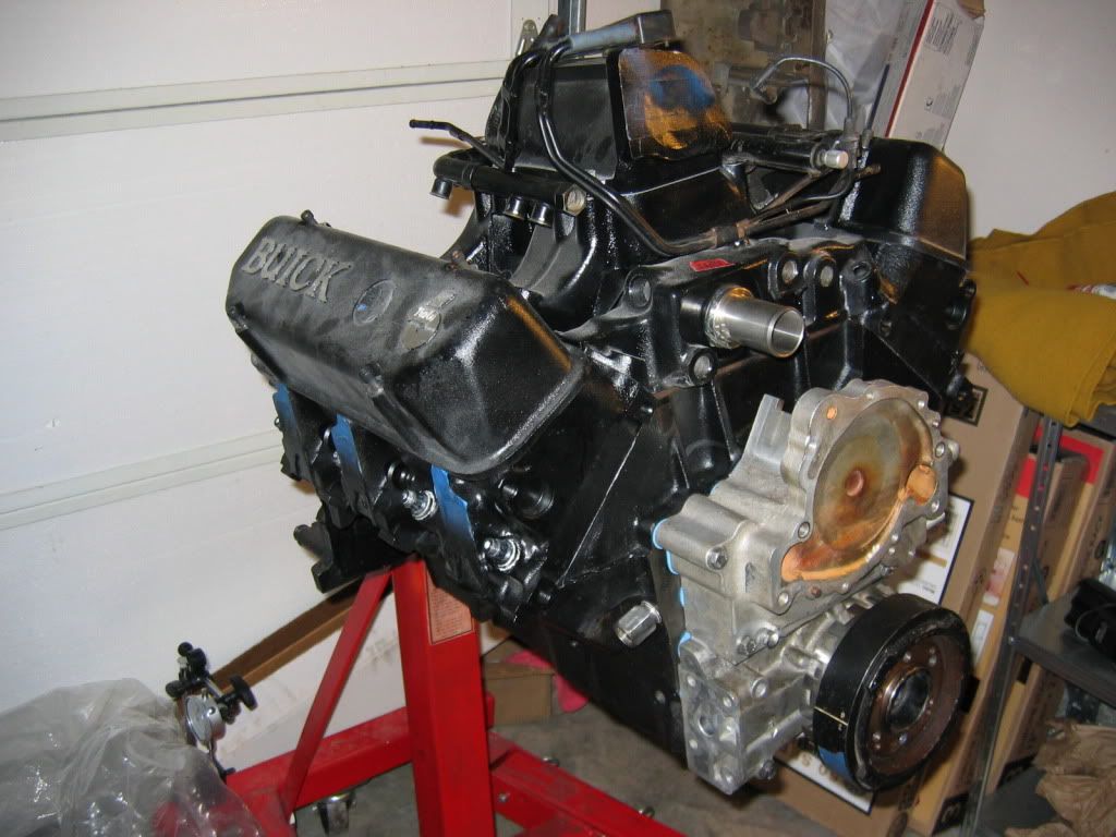
    So I have gotten a ton done on my Turbo6 into '64 Riviera project but I've also run across so many snags along the way I've just started writing them down so when I have to pull the motor again to fix some I can do them all.

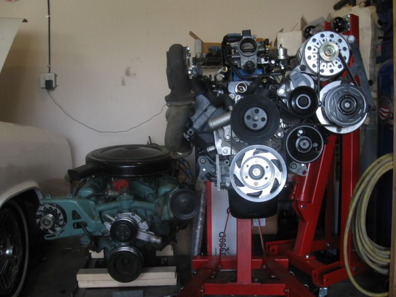
    I have the downpipe and the mid-pipe 90% done, the crossover is around 75% done. The downpipe is missing the bung for the WBO2 and thethe wastegate pipe which I can get away with but I'm trying to get everything done now. The midpipe just needs a pair of hangers and a bend after the resonator so I can clamp the axle section to it when I get to fabricating it. The crossover needs a slip joint added to help with expansion. The bad on the exhaust is that I need to pull everything including the headers to fabricate the wastegate tube and add the bungs.

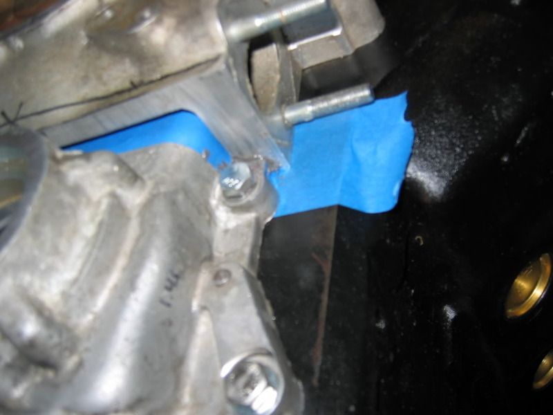
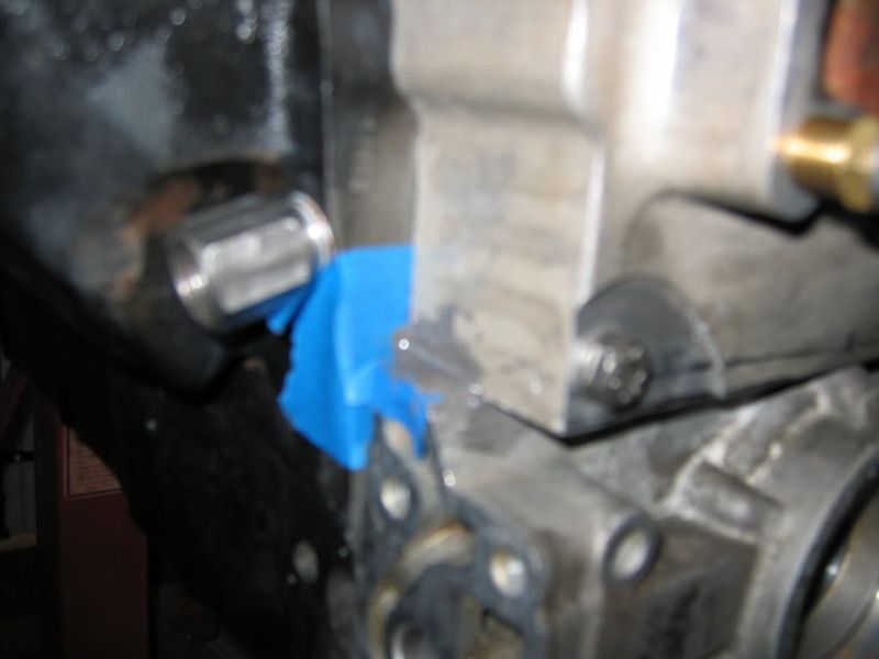
    The trans cooler lines hit the starter, crossover tube, frame, and just about anything coming close so I need to make new ones. At least I have the cooler mounted. It does however mean that I have 2 holes to weld up from the clamps holding the lines and wasted around 16ft of 3/8in cooler line.

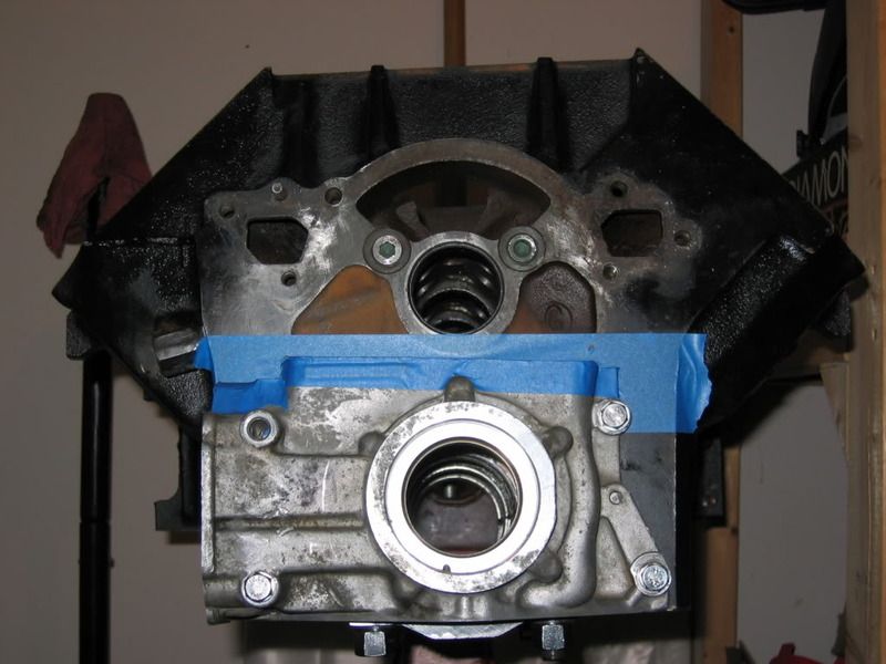
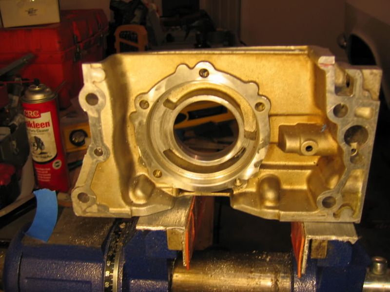
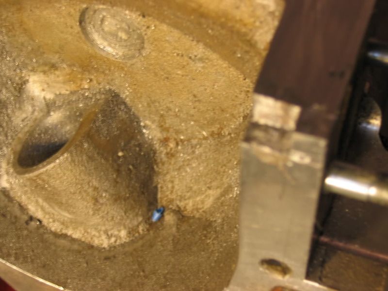
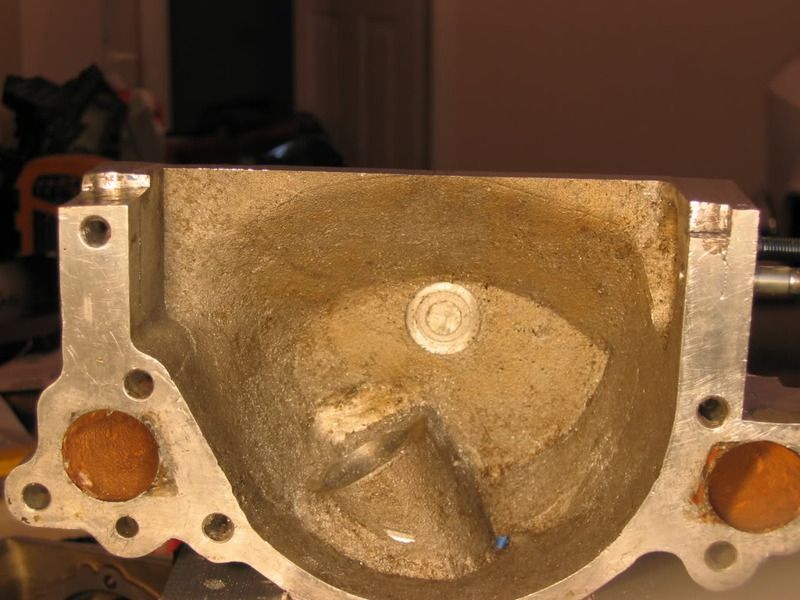
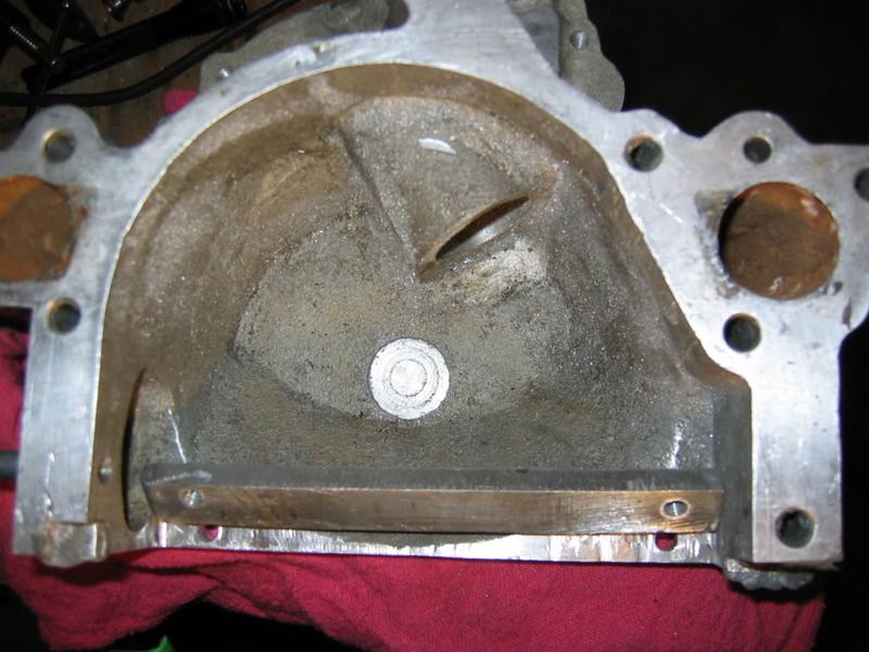
    The transmission is in and thankfully I didn't fill it with fluid after replacing the pan gasket because the engine has to come out because one of the rods hits the windage tray and the drainplug leaks on the oil pan. I am about 2 clicks away from adding an oil cooler and changing my oil plumbing again. I guess this gives me a chance to pretty things up a bit while the engine is out of the bay

    I'm trying to take more piectures so maybe as I dunk the engine again I'll get enough to actually make a documentary of how I did it on photobucket.

    And I thought I was so close.
    Central TEXAS Sleeper
    USAF Physicist

    ROA# 9790

  • #2
    Re: 3 steps forward, 2 steps back

    Hang in there. Sounds like one of my projects only more interesting. Pics are GOOD!

    Dan

    Comment


    • #3
      Re: 3 steps forward, 2 steps back

      CT -- that's one hell of a neat project, I'd love to see the photos of all the custom work you've done.

      It's been a battle for you!

      Brian
      That which you manifest is before you.

      Comment


      • #4
        Re: 3 steps forward, 2 steps back

        Been there! Keep hammer'in away at it. I look forward to some pictures. I request a dash/cluster picture as well as a timing cover picture
        Escaped on a technicality.

        Comment


        • #5
          Re: 3 steps forward, 2 steps back

          Oh I'm staying on this. We're in the last days of the warmish weather and I don't like welding with the door down.

          I've got some pictures of the cluster and the timing cover. I'll get a bunch up tomorrow as a status check type thing. More later when I get the motor out again.
          Central TEXAS Sleeper
          USAF Physicist

          ROA# 9790

          Comment


          • #6
            Re: 3 steps forward, 2 steps back

            Ok, starting with the Timing Cover since it was the longest ago project. Sorry for the long thread and the out of focus pictures but this is archivial stuff and I don't want to take it apart again.

            What I started out with was a pile of 3 Buick timing covers with the need to make 1 that would work on my motor in the frame and I wanted a gerotor pump over the stock wear prone spur gear unit. One stock V6 cover with a hole knocked in it, a stock L36 (FWD 3800 Series II), and a Stage II racing dry sump unit from a local guy who runs a 6-71 supercharged Stage II V6 in a rail. I don't have pictures of the original covers before the cuts but what I end up with was the bottom (oil pump) section of the L36 cover and the top half of the Stage II cover with around 1/4in overlap. The original plan was to weld them together so I made a jig out of 1/2in steel plate that I still have sitting around should I need it but since I had the overlap I decided to just fit the 2 together and use a combination of epoxy to build up low spots and grinding to make a joint that I could seal with aviation form a gasket.
            Here's how it went together:

            Lower section on the block

            That fitting you see sticking out is the oil feed into the block since the oil passages don't line up because of the lower deck height on the FWD Series II block

            Here you can see the backside of the L36 oil pump and the gerotor passages, note the notch on the right side

            The side of the upper Stage II section notched to fit over the corresponding notch in the previous picture

            The other side to fit over the gasket flange on the lower section, note the thickness of the race casting

            Whole backside of the upper section, yes it's upside down

            Right side overlap joint while the JB weld is curing

            Left Side
            I used the painters tape to keep it from sticking to the block or the other piece of the cover. The gap left after I peeled and sanded it off was for the aviation form a gasket to fill. You can see the gap across the middle caused by the different heights of the covers. Here's how I fixed that:

            You can sorta see the spacer propped up between the sides of the timing cover, you can also barely see where I ground out the back of the timing cover to get the piece to sit flat. It's held in place by two 1/4-20 bolts and sealed against the cover with JB Weld.

            Shows how tightly I got it in there, I did this all with a dremel and a high speed cutter


            Here I've filled the oil passage that would take the oil back from the filter adapter to the block with epoxy. Its solid 1/4in thick and I sanded the flange flat with 400grit on glass using sharpie as a guide coat to find the low spots.
            Unfortunately I don't have pictures of the intermediate steps of grinding that spacer bar to it fit the profile of the top of the lower section but lets just say I burned my dremel up (literally it caught fire) doing it.

            To drive the oil pump I took a stock L36 gear and had the timing gear section machined off so it would fit on top of an Edelbrock (Cloyes really) double roller chain after the Rollmaster billet unit hit the backing plate for the oil pump. Note how much I had to machine off.

            Then I machined the back of the balancer down to make up for the difference and put the crank trigger ring in the right spot. I'm using a real Indy Lites balancer with an L36 timing ring bolted to the back


            I've replaced the hex head bolt with stainless button heads, like the oil feed from the pickup gallery to the pump, the index from keyway to ring orientation is unchanged between the 1986 designed EFI system and the 96 OBDII system.

            The finished product in a few different views and states of assembly:

            Lower section in place with gasket

            Both with no pulley and crank position sensor in place

            Side view with balancer in place

            Fully assembled with oil feed adapters in place, semi-custom billet crank pulley (makes up for the change in balancer spacing due to the crank sensor. Sitting next to it is the tired 425 Nailhead that came out of the Riviera. No I am not going to sell it.

            Cluster update tomorrow night or Thursday depending on how tired I am after driving all day tomorrow.
            Central TEXAS Sleeper
            USAF Physicist

            ROA# 9790

            Comment


            • #7
              Re: 3 steps forward, 2 steps back

              Nice work, cool project! Keep up the good work!
              Still plays with trucks....

              Comment


              • #8
                Re: 3 steps forward, 2 steps back

                The tale of my custom dash and gauge clusters

                My Riviera is desperate need of more gauges, to start with I had a speedo and a gas gauge, everything else was lights. Light for engine too cold, light for too hot; not enough amps and finally the parking brake. I built a panel out of aluminum to mount the "big 4" in the stock radio opening, though the gas gauge was not connected.

                This worked well enough for me to tell when I was getting too hot and if the oil pressure was dangerously low but it didn't look right. I also needed a tach and a boost gauge. Here's what I did.

                Start out with the stock dash panel section


                Notice the area that looks like it could have a tach in the middle of the right "gauge", I looked into it but the gas gauge completely blocks it. Let's take a look at the back to see what's in the way back there.

                Oh boy, lots of printed card circuits, I'm not messing with that. Good news on the electrical stuff though the factory manual is very very detailed about what is what and I had it decrypted in around 5min.

                So I popped out the multifunction warning center thing and the clock in the top middle and began test fitting my 5in Autometer Designer Black tach and the matching Designer Black boost gauge.

                You can see the amount of light pipe like structure on the inside of the hole for the tach. I had bought a spare carrier to cut up but it was a cruise control carrier so had extra holes and relatively rare so I just cut up my original since it wasn't perfect anyway.

                There now it's out of the way

                To hold the tach in place I took the backing ring that held the original plexi labeling disc to the bezel and pie cut it so the entire tach would slip through and rest on the back side if the chromed bezel on the tach.


                I didn't take pictures of the rest of the work I did on clearancing the inside of that bucket, relocating the hold down spring for the bezel or running the wires out the back of the bucket to connect to an external tach wire and using ring terminals to pickup signals off of the stock wiring plug.

                What it looks like from the front.

                With that done I got to work on the boost gauge in the clock position. This was a lot more work on getting it in there as the tach was pretty simplistic on how to mount it and what to cut. The tach is held in by a hook at the top and a set screw holding the bottom of the bezel down. The clock as held in with a pair of ears snapping into spring retainers.


                Notice the clock mounting cup is larger in diameter than the boost gauge; the gauge would fall right through so I had to put it into the mounting cup somehow.

                So I cut the gauge apart and this is what is inside of an Autometer mechanical boost gauge.

                To make it short I basically cut the stock clock mounting cup apart so it would keep the rim to bolt to the back of the bezel and then hold the boost gauge cup in place.


                I ditched the chrome bezel of the Autometer gauge but kept the lenses as they didn't have clock markings on them and used the "around the dial" lighting to get light onto the face of the gauge.


                The whole assembly is held in place using the mounting clamp from the gauge to hold the gauge against the carrier. Here's what the whole setup with wiring looks like from the back:

                The wires running off to the outside run to the gas gauge mounted in the console and the interior lights since I didn't find a way to tap into the stock wiring without cutting it up. I tested it with the nailhead and it worked great!

                Here's what it looks like in the car with new (I didn't take any pictures of the assembly of it) console gauge cluster made out of an extra radio mounting plate, some sheet steel, and JB weld body work.


                Yes I will be doing the speedo at some point but its $240 and the stock one works fine still so when I'm done with the have to haves and have $240 I'll take care of it.

                Enjoy and I'll be doing the exhaust downpipe chronicles next.

                Central TEXAS Sleeper
                USAF Physicist

                ROA# 9790

                Comment


                • #9
                  Re: 3 steps forward, 2 steps back

                  neat! that timing cover is nutso

                  Suggest you resize the pics to 720 pixels wide before posting them...then we don't have to scroll....

                  My fabulous web page

                  "If it don't go, chrome it!" --Stroker McGurk

                  Comment


                  • #10
                    Re: 3 steps forward, 2 steps back

                    Fixed, they are 800x640 now, too many to change to 720 manually.

                    I also fixed the appostrophe error, looks like the forum doesn't like it when you cut and paste from a word doc into it.
                    Central TEXAS Sleeper
                    USAF Physicist

                    ROA# 9790

                    Comment


                    • #11
                      Re: 3 steps forward, 2 steps back

                      Nice job! I wouldn't change the speedo though - part of what makes it a Buick is the speed minder.

                      Dan

                      Comment


                      • #12
                        Re: 3 steps forward, 2 steps back

                        I just noticed it, but I took that last pic while the Nailhead was running, might have been one of the last times it was. Idling at 700rpm with 14in of vacuum and that's with an almost dead cylinder!
                        Central TEXAS Sleeper
                        USAF Physicist

                        ROA# 9790

                        Comment


                        • #13
                          Re: 3 steps forward, 2 steps back

                          I remember talking with you about the 3800 pump 4 years ago , I think the stock pump isn't too bad if you don't drive the car much
                          I hope it works for you

                          Comment


                          • #14
                            Re: 3 steps forward, 2 steps back

                            Originally posted by DanStokes
                            Nice job! I wouldn't change the speedo though - part of what makes it a Buick is the speed minder.

                            Dan
                            Give me enough money and I wouldn't mind having someone convert a stock speedo plate into a tach with custom plexi face for numbers so it'd match the speedo. But I'd also like them to convert the speedo into an electronic unit so I can run it from the computer since the 4L80E doesn't have a mechanical drive. Right now I'm going on vacation then when I get back I'll take a stab at getting the exhaust done so I can complete that write up.
                            Central TEXAS Sleeper
                            USAF Physicist

                            ROA# 9790

                            Comment


                            • #15
                              Re: 3 steps forward, 2 steps back

                              Love them old Buicks, good luck with the project!

                              Comment

                              Working...
                              X