Originally posted by dave.g.in.gansevoortView Post
I've got a nephew with a 400 sbc probably 600ish hp looking for a home. Want me to ask if he'd lend it to you? It was supposed to be in Jim's hillclimb special. And if you need "More Power R R R" I've still got my Hilborns...
Love the Studilac. Spot on on the suspension recommendation above.
Thanks but no thanks. I have a plan in mind once the bits start coming together. But no announcement 'till the project is in my hands.
Originally posted by dave.g.in.gansevoortView Post
I've got a nephew with a 400 sbc probably 600ish hp looking for a home. Want me to ask if he'd lend it to you? It was supposed to be in Jim's hillclimb special. And if you need "More Power R R R" I've still got my Hilborns...
Love the Studilac. Spot on on the suspension recommendation above.
Not much to do on the rig but draw some parts in my off time. A while back I saw a picture of a fender emblem used on an original Frick Studillac. I changed my profile pic to that one! After som searching I found one more picture of the emblem. Frick put Cadillac engines in new Studebakers from 53 to 55 and there are only 3-4 cars still around. The emblems are unobtainable so I decided to draw one as best I can and possibly use for a paint divider if I two tone the roof. The font on the valve covers or horn button might be cool as well. On another note, somehow my frame drawing disappeared! I have all the parts it looks like but it will take a while to piece it back together. It comes in handy to help me visualize things when I get to thinking about something and am away from the shop.
4Photos
Last edited by 53 Studillac; April 9, 2022, 06:06 AM.
My project got picked for the weekly "What are you working on" section on Stacey David's Gearz Facebook page. I'm at work so not sure if it got mentioned on the show. It's cool to be recognized! Check it out. Stacey David | Facebook
Last edited by 53 Studillac; April 17, 2022, 05:22 AM.
alignment plates and something that allows the wheels to slide. My first 'tools' were nothing more then some 1" angle iron and 4 of those no-stick, teflon baking sheets...
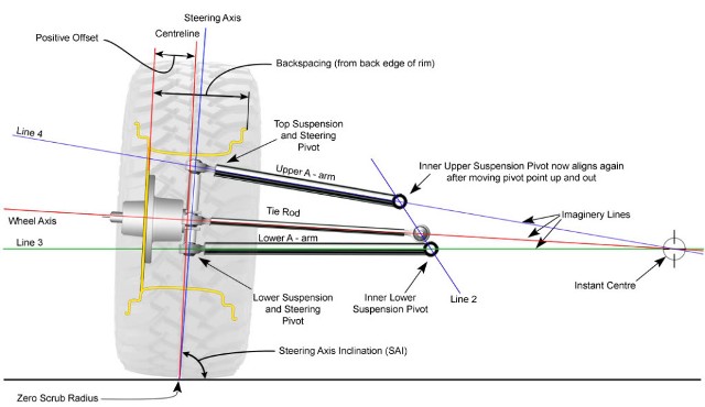
that said, you can also do bumpsteer checking with a tape measure. See the attached picture - your camber should be at least 1-2* don't worry about castor at this point but eyeball 5* from vertical leaning towards the back of the car. In this moment, close really does count. Most times the biggest problem (especially on old cars) is you can't get enough negative castor.... why that's important is it affects bumpsteer.
The other important thing to measure is ackerman - how much the inner tire turns in relation to the outer tire. You want the inner tire to turn more because its circle is smaller then the one travelled by outer tire. If you get it the same or worse, less (inner), then it will literally take you 40 acres to turn your car around.
I haven't had much time to play with the car this time home but enough to run some alignment questions your way. I modified my lower control arms and changed ball joints to lower the car 2". This may bite me in terms of bumpsteer, yet to be determined. I assembled the front suspension again and tried to take some measurements that causes some concern. WIth the upper control arms pushed all the way inward, I still have about 1/2 degree of positive camber (top of tire leans out). I think I need at least 1 degree of negative camber? I also found that the adjustment slots for the upper control arms do not allow but maybe 2 degrees of caster. Trying to maximize the castor also added more positive camber. And it seems I should try to get 5 or 6 degrees of positive caster.
I'm still working on verifying what I can do with bumpsteer as it currently sits, but think it may be better to go ahead and make some other changes/fixes to make it better while I am at this stage. Thinking back I never did get to drive the car with the Flaming river rack and current control arm configuration.
I read over SBG's PFTEW's C6 front suspension install and other research and think I may need to start over one more time to end up where I want on the front suspension. I may look at a C5/6 spindle and lower control arm, but do not think I have the necessary room for the longer upper control arm from the Vette. The Corvette hubs and brakes would be nice too! The longer lower control arm should be better but only if I can mount the rack in the proper place to minimize bump steer. This could require a custom rack. I also think I will need a custom steer arm. No way I can mount the rack high enough unless I move the engine back several inches, which would cause all sorts of issues under the dash. I also think I need to change the upper control arm mount so the castor can be in the 5 degree range without need of shim adjustments and allow proper camber as well.
It kinda sucks to have to spend money to re-do this! And I may find that I can get similar results using the Wilwood spindles I have.
Another question is about the turn plates. I have solid links installed in place of the coil-overs. Can't I turn the wheel to take measurements with the tires off the floor where I can turn them smoothly without the need of the plates?
The next think I want to tackle is to get the body back on the chassis and verify that the ride height is where I want it now and if so I will have a good starting point for the redesign.
Last edited by 53 Studillac; May 13, 2022, 10:52 PM.
I am not sure who's front end stuff you are using now but you MIGHT be able to find some adjustable upper control arms that would allow you to get the camber and caster numbers you are shooting for. As to bumpsteer, one way to deal with this is to go away from conventional tie rod ends and use hiems. For most popular spindles, you can buy bumpsteer kits that allow you to adjust the height of the tie rod to help minimize bumpsteer.
I already have a bumpsteer kit on it that is spaced down the max. I can team the steer arm for a standard bolt to allow for longer adjustment but if I tilt the spindle back enough for the 5 degrees of castor it will be longer that I really like. I can make a new steering arm to eliminate the extreme extension. And agree on the adjustable control option. I do think it would be much better to make the mount for the control arm vertical from the frame rail and shim adjustable to better maintain alignment. Thanks. I listening to get all the information I can to try and get this corrected.
-1.0 to -1.5 is optimal, at least 5 degrees of castor 7 is better
you know those teflon cookie sheets? you can buy them for a couple bucks each at any grocery store - those work quite well as turn/slip plates
the Mustang 2 suspension has a problem maintaining alignments because of that slip design - on a light car, it's not as bad, but on something with a 500 ci Cadillac... well, you're moving the right direction in solving the alignment issue - if you use what CST is recommending, you can solve two problems with one solution
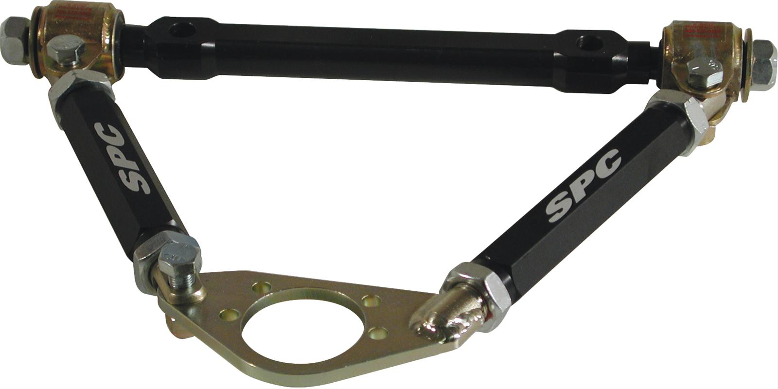
Free Shipping - SPC Performance Adjustable Control Arms with qualifying orders of $99. Shop Control Arms at Summit Racing.
what is the track width of your car? The C5/C6 stuff required 2" flares on the C3, so you may wish to check that issue... but you can get a custom rack, however, the arms are a lot longer then a M2.... fun stuff, isn't it?
-1.0 to -1.5 is optimal, at least 5 degrees of castor 7 is better
you know those teflon cookie sheets? you can buy them for a couple bucks each at any grocery store - those work quite well as turn/slip plates
the Mustang 2 suspension has a problem maintaining alignments because of that slip design - on a light car, it's not as bad, but on something with a 500 ci Cadillac... well, you're moving the right direction in solving the alignment issue - if you use what CST is recommending, you can solve two problems with one solution
Free Shipping - SPC Performance Adjustable Control Arms with qualifying orders of $99. Shop Control Arms at Summit Racing.
what is the track width of your car? The C5/C6 stuff required 2" flares on the C3, so you may wish to check that issue... but you can get a custom rack, however, the arms are a lot longer then a M2.... fun stuff, isn't it?
Just something to think about with that style a-arm. When on the brakes, that weld on the balljoint plate is the only thing keeping the spindle from moving forward or backward depending on if it's behind or in front of the balljoint. The other 3 points on the triangle are all bolted joints and are not going to resist any force front to back on the a-arm. Could make for an interesting panic stop...
Originally posted by dave.g.in.gansevoortView Post
Just something to think about with that style a-arm. When on the brakes, that weld on the balljoint plate is the only thing keeping the spindle from moving forward or backward depending on if it's behind or in front of the balljoint. The other 3 points on the triangle are all bolted joints and are not going to resist any force front to back on the a-arm. Could make for an interesting panic stop...
I don't race sprint cars, but those come from that world - where adjustment is everything - but I see what you're seeing, I dunno, maybe have $274 mock up arms?
Kinda hard to solve the concerns here without actually looking at it. A couple things: From the photo it seems like a modified or altogether new upper a-arm is in order, or something with enough adjustment to work; jig up the bare spindle where you want it in terms of caster/camber at ride height and fab upper a-arms to fit, aiming for fasteners being in the middle of the adjustment slots. (Maybe an engineer could work out in a few minutes how much stress is on the welded area of the pictured adjustable units.) The struts instead of springs will work fine hanging in the air to do measurements, zero degrees camber there will probably turn into a half-degree negative with the car on the ground and five degrees caster is IMO a good angle to shoot for. Caster doesn't cause bump steer problems, anti-dive geometry changing the caster throughout suspension movement does. Just aim in the middle i.e. all geometry good at ride height, knowing it will change under acceleration or braking. With the rack at such a lower position than the steering arms are designed for I'd sure make new ones that eliminate the spacers, once you have your height known. (I'm assuming the tie rod length is appropriate, such as if the rack is even height-wise with the lower control arms then the tie rods should be the same length as those parts.) Ackerman will have to be paid attention to at that time, looking from above there should be a straight line from the center of the rear axle, through the front ball joints, to the steering pivot, also looking from above the tie rods should angle forward a bit. Sounds like a job for a guy who works w/ CAD (wink) and then a machinist with a block of cold-roll steel and a taper reamer. With that, if you'd rather be just fixing issues and not start a whole new project I'm sure the Mustang II/Wilwood stuff would be fine once you had those aspects worked out.
what is the track width of your car? The C5/C6 stuff required 2" flares on the C3, so you may wish to check that issue... but you can get a custom rack, however, the arms are a lot longer then a M2.... fun stuff, isn't it?
As it sits I have 57.5" wheel mounting surface to wheel mounting surface. I was thinking I could relocate the lower control arm pivot farther inboard to keep the track close to where it is but allow for the longer arms. And by doing so I would probably need a rack with custom tie rod pivot spacing.
 Tweet
Tweet

Comment