 Tweet
Tweet
Man it was hard paying the $570 for the turbo (cheap in turbo costs, it is used) however that's probably the second largest outlay I've done for a single piece of the car behind the CNC ported heads.
-
Central TEXAS Sleeper
USAF Physicist
ROA# 9790 -
They're here!!! Of course it's raining off and on today so MAYBE I'll get a picture of the stuff today. If not, tomorrow!Central TEXAS Sleeper
USAF Physicist
ROA# 9790Comment
-
The rain let up an the sun came out long enough to take some snaps
What I got today:
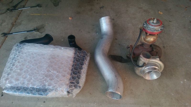
TURBO!!!
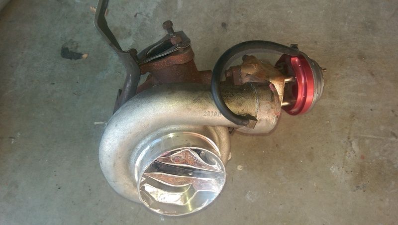
It's a classic 60-1 Buick unit that has been upgraded to a Garrett ceramic ball bearing center section
Intercooler
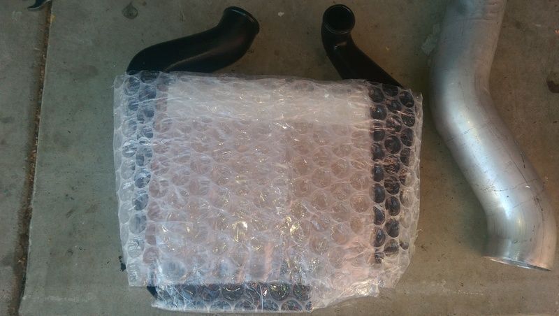
Just a stock LC2 intercooler, just happens to be one off of a 37K mile show car that the guy decided was worth more in parting it out to restoration people than selling whole or something.
Inlet Tube
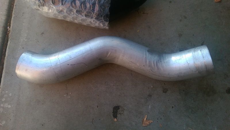
4in mandrel bent inlet tube from the turbo to a cone filter Might have to get some adapters and couplers to put the MAF on it and attach it to the turbo
The included wastegate is a Turbonetics Deltagate MkII and is a 44mm unit vs the 38mm unit I have now. Not only is it pointless to run two of them but the flange on the turbo housing actually runs into the other wastegate on the down pipe. Solution... Unsure but likely use the one on the housing and refab the downpipe to match up.
Will have pictures of it mocked up tomorrow most likely. Unlikely I'll have the intercooler in but we'll see.Central TEXAS Sleeper
USAF Physicist
ROA# 9790Comment
-
Nice!Escaped on a technicality.Comment
-
Well the wastegate is turning out to be a big pain! The Deltagates that I have and actually have a setup for using are ~35mm on inlet and outlet of the valve and uses a 2 11/16in center to center with 10mm bolt pattern. The monster that came with the turbo has the same Deltagate top as the small ones I have and even the same part number but the valve body is WAY different and has 44mm openings and a 2 3/4in center to center with 12mm bolts.
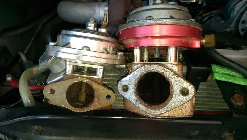
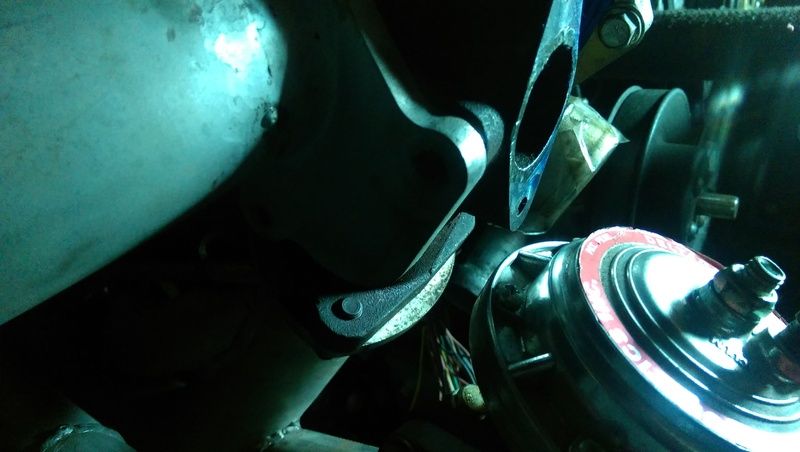
Additionally, the large valve mount is welded to what was a 35/38mm wastegate pad and the pad sticks out far enough to foul the wastegate I had on there by a good inch or so.
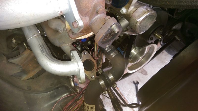
The resolution is especially frustrating since the large 44mm 2-bolt wastegate pad isn't supported by anyone that I can find. The "simplest" solution is to pull the housing off and machine the 44mm riser off of it to get the pad out of the way and so I can put a block off plate on it then just use the smaller gate that I've had sitting there in expectation of a turbo. Blocking off the two pads for the smaller gate would also work but that leaves me with an unmuffled wastegate and as cool as I know some friends would find it... I'm not particularly interested in that. Additionally anything involving the larger gate will require fabbing up a flange to mount a pipe too.
Quick searching says that a bigger gate is to run LOWER boost since you need to bypass more gas. The motor is built to take a goodly portion of boost so I think I'll be running it around 10psi or so min and the smaller gate should work. The hard part is convincing myself to take my brand new (to me) turbo and take a sawsall and mill too it.Central TEXAS Sleeper
USAF Physicist
ROA# 9790Comment
-
and now on the front page Doing it all wrong since 1966
Comment
-
Thanks for all the nice comments on the front page and the love for the car!
Plans for right now are to keep plugging away on my original list of things to fix (now down to shifter cable and front brakes) but I've added fixing a few things that have been bothering me along with doing the turbo install such as adding a breaker to the front to rear power line and installing the 2000 Eldorado buckets I've been packing around.
Like I mentioned in the blog, I've decided that since I can't find a flange for the bigger wastegate (turns out it's a Racegate and I sort of found a flange) I'm going to cut it off with a sawzall then machine the pad down. I'll measure the hole underneath and see if I want to put a freeze plug down it before I put the block off plate on it.
Brakes I need to buy an ISO/Bubble flare kit so I can make the ends for the master cylinder and the ABS unit that I'm putting on now since I'm plumbing brakes anyway. If I have the time/budget I'll get the adapter rings to fit the B-body reluctors onto the 71-76 Riviera rotors but I'm not worrying about the front sensors or the rear reluctor and sensor till later.Central TEXAS Sleeper
USAF Physicist
ROA# 9790Comment
-
ISO/Bubble Flare Kit has arrived! I've also played around with the original mounting bracket for the ABS module and with some relatively simple cutting and bending I should be able to get it into a shape that will work to hold the module clear of everything and not look too bad. There is no hiding it.
The big problem I'm having is the brake pushrod on the master cylinder. The stud on pedal is pressed or otherwise hard mounted to the pedal arm and it's 7/16in. The big problem is gap between the pedal and the retaining groove for the clip is only 3/8in wide. For an eyelet that would be fine, but due to how short the pushrod is I want a rod end with a spherical bearing. The narrowest rod end with a 7/16in bore is also 7/16in wide and ~$40. The regular <$10 rod ends are 9/16in wide. Neither are really going to be able use the retaining clip, so I'm thinking of making a clip/strap that wraps around the stud and the pedal to guarantee that the rod end stays on the pedal. Thoughts?Central TEXAS Sleeper
USAF Physicist
ROA# 9790Comment
-
I really hate whoever put that wastegate thing on there! The welds were rockhard material and I knocked the corners off of two end mills before just giving up and running a cut off wheel back and forth over the surface (still chucked up in the mill) to smooth it down then hit it with a file to level it up. I'll seal the block off with copper RTV anyway. Glad that blasted step is done. Pictures tomorrow, now it's bedtime!Central TEXAS Sleeper
USAF Physicist
ROA# 9790Comment
-
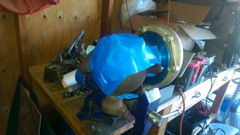
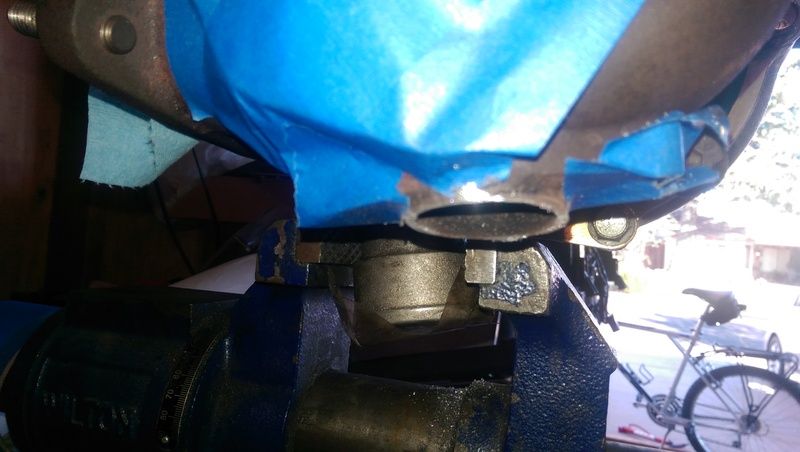
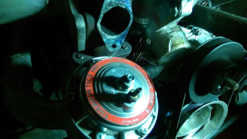
So here's what I ended up doing. I couldn't get the turbine housing (hot side) of of the turbo with a level of force I was willing to exert on it so I stuffed the housing full of paper towels, taped over all of the bolt holes, plugged the vacuum ports, and most importantly taped plastic over the oiling section.
 [
[
You can see I put the opening down so gravity pulled as much of the chips from the sawzall out. Not sure why I put so much effort into that step since I could only put it upright on the mill.
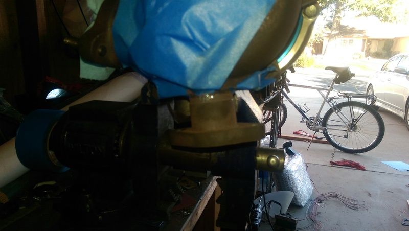
Then over to the mill
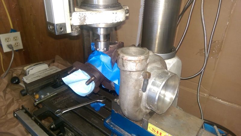
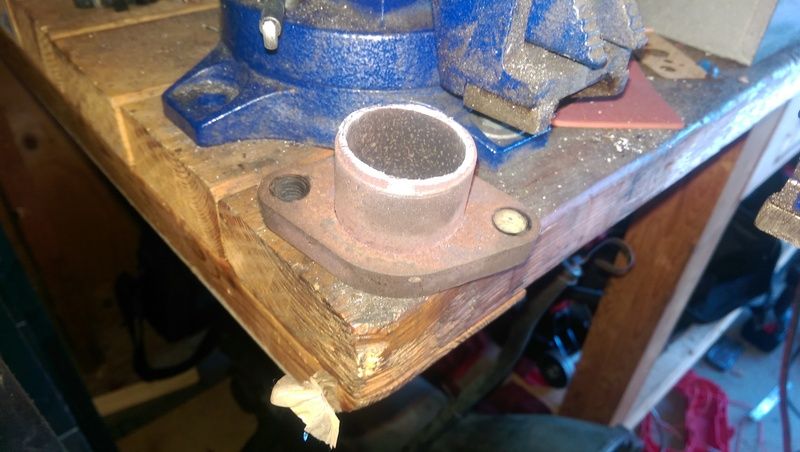
At this point I stopped taking pictures and spent 3hrs experimenting with leveling, clamping, and how to cut the silly stub off. Like I said last night I ended up using an abrasive cut off wheel (1/4in mandrel) in the mill to first cut off most of the offending pipe then after breaking 2 end mills I just took to running the cut off wheel slowly over the surface to smooth it out.
Sorry for the bad lighting but it was 10PM and I did what I could with the shop light.
Central TEXAS Sleeper
USAF Physicist
ROA# 9790Comment
-
Things have moved forward a bit. The turbo now has an oil drain line going to the pan (what a fun story that is of how I changed hose ends, found it was too long, then cut it, then realized that using a straight hose end made it share space with the lower radiator hose, then putting the very hose end I removed back on to get it around the radiator hose... 2hrs of fun). That's all I can really claim credit for doing with the guys over for fellowship but it was a great time!
Since then I've managed to order most of the needed parts which are slowly filing in. I have the oil splitter block (-10 'T' with a gauge port on the side) mounted, the lower radiator mounts modified and halfway mounted (need to put another set of self tapping screws in), and pull the transmission cooler lines so I can refab them to clear everything. No pictures because when you have 40min an evening to work it's get things done rather than take pictures. Hopefully Friday afternoon I'll get some of what's been done. This weekend I'm on solo-daddy duty so I'll probably just do some CAD work so I can send my caliper adapters out to the waterjet shop for fab and all I need to do is machine the different "levels" into it.Central TEXAS Sleeper
USAF Physicist
ROA# 9790Comment
-
Pictures as promised:
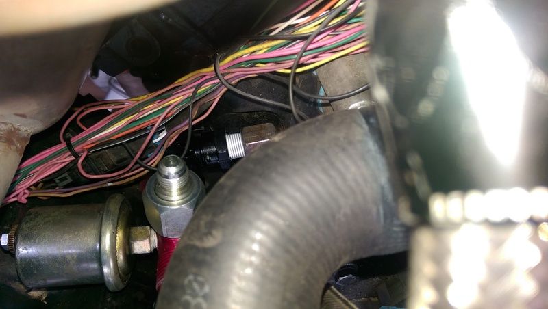
You can barely see the 90�, double swivel, 3/8-NPT to AN-10 female adapter threaded into the block oil supply fitting. Because of a failed attempt to oversize the port to 1/2-NPT, that's a billet adapter that keeps the oil out of the water. I can't really reef on it hard so it got a solid coating of teflon on the threads.
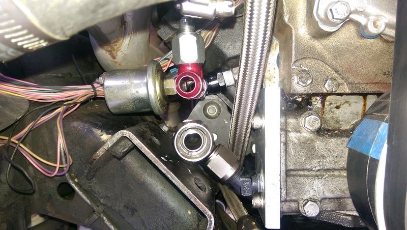
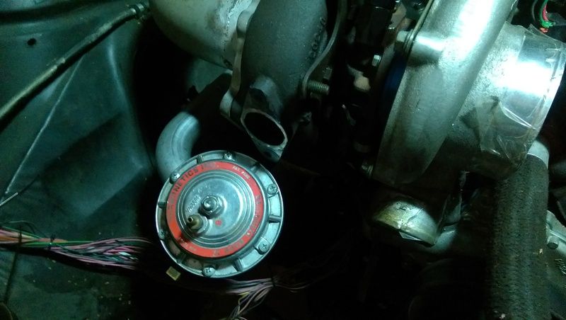
There it is again, this time looking down underneath the headers. You can see the AN-10 'T' that splits the oil out to the turbo (up with an AN-10 to AN-6 adapter on it), the oil pressure transducer (goldish can off to the side), and to the block (straight on back). The lower hose end you're looking down the end of is the oil exit from the pump going to the remote filter that's mounted on the lower radiator crossmember. If I add an oil cooler, it'll be between the remote filter and the 'T'.
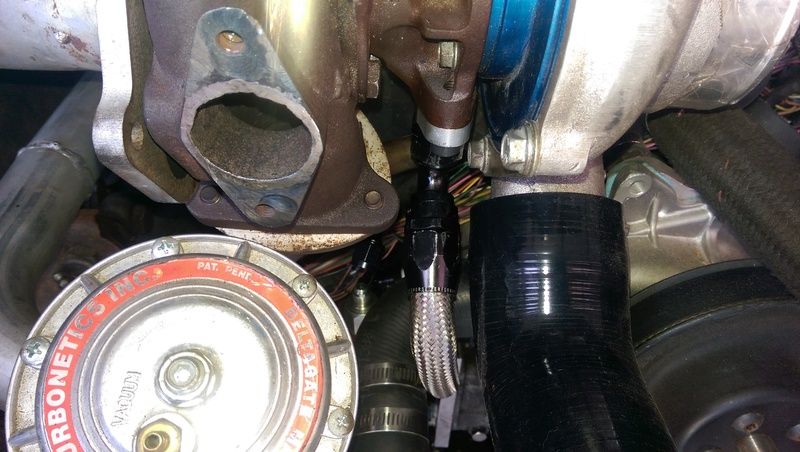
Turbo drain line, yes it's a little tight but I need to reclock the housings anyway. I'll snap a picture of where it goes on the side of the oil pan at some point.
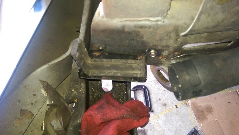
Very unimpressive but that's the lower radiator mount. It keeps the radiator as high as possible so the underside can serve as a scoop and keeps the lower radiator hose from hitting the strut rod bracket on the frame.Central TEXAS Sleeper
USAF Physicist
ROA# 9790Comment
-
Caliper bracket designed in SolidWorks and ready to send off to the waterjet shop for quote and construction. Top and bottom most holes are to bolt to the spindle while the middle two are to bolt to the caliper. When my SolidWorks skills improve I'll draw up the spindle and caliper.Central TEXAS Sleeper
USAF Physicist
ROA# 9790Comment
-
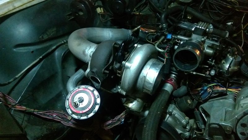
Just to be a bit of a tease...
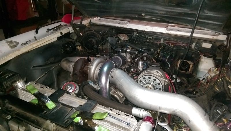
The intercooler and radiator are in there but like you can see, the radiator is held in place with clips and most of the rest of the tubing is just slipped on or dangling considering I cut the up pipe too short since I didn't measure over the top of the inlet pipe for the turbo... Oh well, I have a spare 2.5in Al elbow.
Central TEXAS Sleeper
USAF Physicist
ROA# 9790Comment
-
Tonight's update:
In the teaser picture you can see the uppipe and the turbo inlet are fighting for space so I had a 1/2in phenolic plenum spacer sitting on the shelf and tossed it on along with an RJC Powerplate. This pretty much solved the interference and allows me to keep the up pipe out of the hood though it's close. The downside is that the vacuum block on top of the motor now hits the hood (or is 1/8in away max). Solution is to fabricate. Take piece of 1/4 or 3/16 aluminum plate and block off the vacuum ports on the top of the throttle body and then drill and tap the side of the plenum to continue to be able to draw vacuum for things like the HVAC, fuel pressure regulator PCV, ect. I like the scheme even though I'm long term planning on dropping the motor a good 1.5in when I redo the motor mounts next. Now I just need to decide if I want certain things to share a vacuum source.
In smaller related news I got the last of the old trans cooler lines out, the remote oil filter bracket in place, and finished up the lower radiator mounts. If I have time this weekend I'll finish up the upper radiator mounts and decided between leaving the MAF in draw through behind the filter in the old battery box area or blow through in the uppipe. There seems to be a lot of good reaction to putting the MAF in the uppipe both from the Turbo6 guys and the turbo L67 folks. I'd have to do a 2.5in<4in MAF>2.5in coupler chain but it would mean that I'd not have to cut up my other 2.5in 90 since the splice of the MAF would fit just fine with the scraps of what I've already cut up and would need to cut again.Central TEXAS Sleeper
USAF Physicist
ROA# 9790Comment

Comment