Edited inline and just to be a post monger, I'm bumping it to put them in...
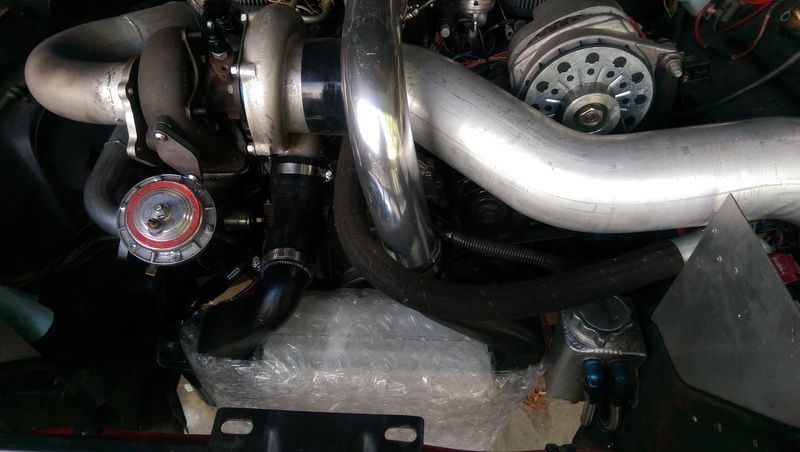
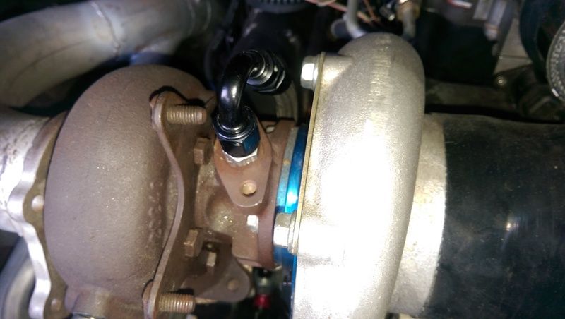
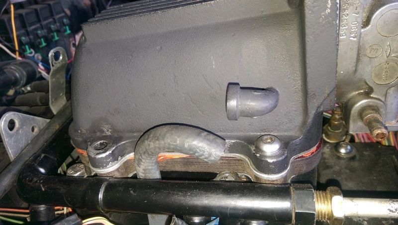
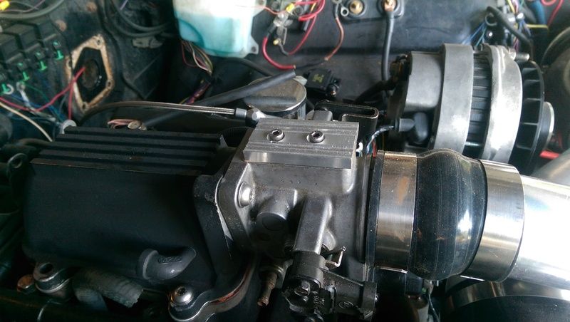
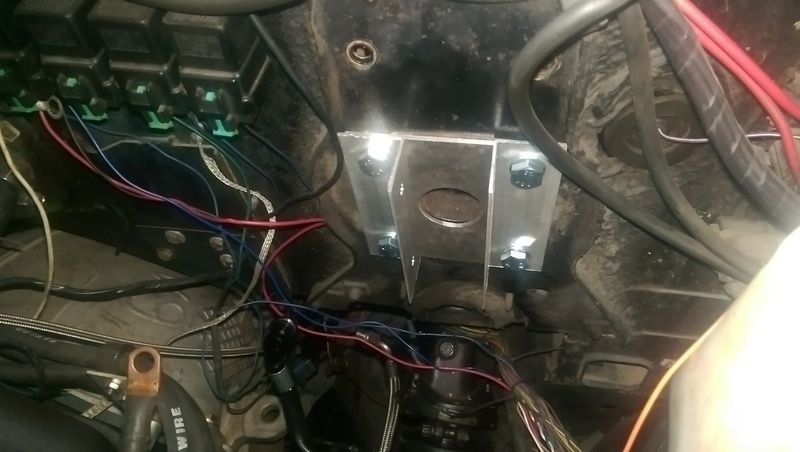
Overall shot showing that the turbo, intercooler and plenum pipe can all happily coexist now. What I didn't take a picture of is the billet vacuum blockoff plate that I machined up for it. I'll catch that later sometime I'm sure. Oil hoses sneaking behind the intercooler too and from the block. That top one I'm a bit concerned about so I'll keep an eye on it for oil leaks. Oil supply is heading to the turbo now from the oil block down low. That's the PCV vacuum port relocated to the side of plenum to cut down on the hood clearance issue since I'm now running that 1/2in plenum spacer. The rest of the vacuum ports come off of the back of the plenum. I've got half of the vacuum fittings but not screwed them in yet since I only want to do that once with the PTFE paste. You can also see the plenum spacer sitting under the plenum peaking over the top of the fuel rail and the coil pack hold down bracket that I've bent out of the way and might have gone too far to bend it back into place without snapping the aluminum.
So one of my coworkers who started 1wk after I did has a 3D printer so I asked if he could print me up a prototype brake caliper bracket and he did! Revealed I needed to do some tweaking to minimize the amount of work I have to do after I get the blanks from the waterjet.
Work has been getting done, just not really taking pictures as I go.
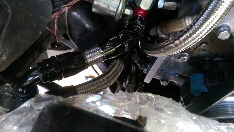
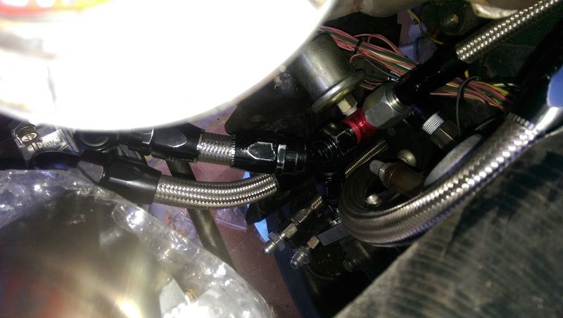
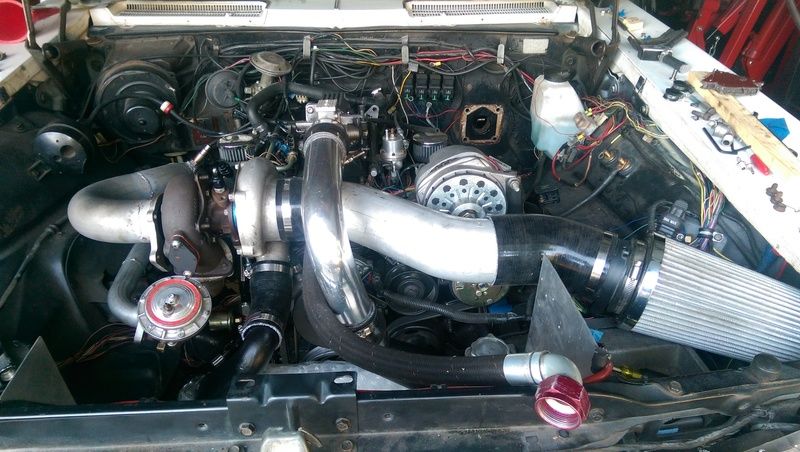
Here's the summary of what has gone on recently. The turbo system is all but plumbed. I need to get some good hose clamps for the plumbing, reattach the downpipe and wastegate, and hook the MAF back up. I do need to double check all the vacuum connections but that will be part of the pre-start checklist. Not pictured in the progress is a bracket down in the bottom right that holds the inlet tube up so the filter doesn't rest on the top of the computer. I also need to build a scoop for the intercooler but I can't get on that till I get the radiator mounts figured out since it's roughly a 3x20in slot under the radiator... Actually as I say that, why don't I mount the radiator to the scoop inlet?
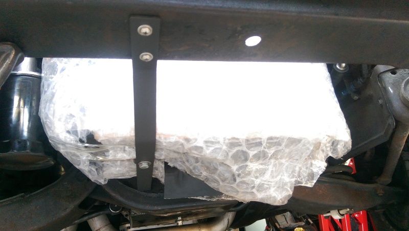
I mounted the intercooler and had a good time making the bracket with my 6yr old. This bracket holds the intercooler up and keeps it centered between the oil filter bracket on the passengers side and the power steering reserviour on the drivers side. I've got perhaps 1/8in clearance on the drivers side but wiggling the intercooler around doesn't hit so I'm hoping it doesn't rattle.
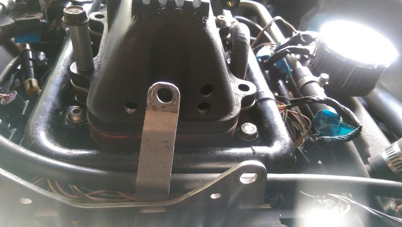
A while back I mentioned machining up a blockoff plate for the vacuum block attachment on the top of the throttlebody. Here it is.
Made some more progress today. Might make some more tonight but daylight is running out so I thought I'd put up what I've done anyway.
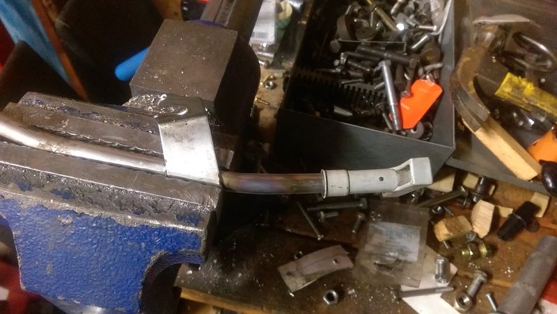
The uppipe (intercooler to throttlebody) was hitting the edge of the hood bracing. I've been trying to keep the height down so I can either put a stock hood pad back in or preferably get a GN hood pad and cut it down to fit in the spot as an extra factoriesque touch. I trimmed the hood brace down with a 2in hole saw using a piece of scrap aluminum c-clamped to the brace as a centering guide. Taking it in nibbles (thanks Project Binky!) allowed me to cut through the edge without it biting and skipping about.
Another something I forgot to mention yesterday was how I wanted a new throttle cable bracket. I guess I overlooked it since I do have a totally hacked together stocker that works but I want a new one.
Hard to tell but that's it after I primered it. I'll admit that I got ahead of myself with the paint, there is no hole for the throttle cable to go through nor did I really round off the corner like I wanted to... Oh well, I'll just paint it again after I'm done.
Been a while but work has been rolling on. Of note, my cellphone has officially surpassed my regular camera by an order of magnitude in how well the autofocus works... I tried using my camera to take pictures and it won't focus worth crap on smaller objects.
Anyway, the big news I can share without having any pictures is that I've been able to bring my Optima redtop back from the dead with some help from my Suburban. Reading up on them I found a DIY desulfination process using a good battery and a charger. Basically you use the high voltage from the good battery to both kick the reaction off and fool the charger into thinking there is a live battery in the system. I used my Suburban since it's the closest to the garage door and ran it to get the resting voltage up to ~14.5V to kick the reaction off. I could feel it slowly start to heat up from the negative terminal over to the positive terminal over the course of an evening. 2 days on the Suburban then 16hrs on the charger I checked on it and heard it bubbling so I killed the charger and it's back to normal. Going to have to be careful not to overly discharge it and charge it a bit more gently in the future but I have a functioning redtop again and that's doubly good since that's what my billet battery hold down is design to support in the trunk.
If you want that Optima (or any lead acid battery) to last longer find a trickle charger or solar charger that will keep it at "float" voltage when you're not using it. Float voltage for a lead acid battery is 2.17 volts per cell (13.02 volts for a 12v battery). I have a deer feeder charging solar panel that has a built in voltage regulator that I use on my deer lease truck that sits for 9 months of the year. Before I found this solar charger my batteries only lasted 3 years or less. The current battery is over 6 years old. I installed commercial battery power systems for over 20 years and those batteries lasted decades. The only time we replaced a set of batteries was when more amperage (larger batteries) was required. The reason these batteries lasted so long was they were always kept at 2.17v per cell with charging rectifiers that monitored the load and never allowed the batteries to get below 2.17v per cell. Before they were put online we charged them for 40 hours at 2.5v per cell and monitored the specific gravity of the battery acid/water to make sure they had the right mixture of acid and water.
Thanks, I'll have to check into something like that. The charger has a "hold" setting but that might not be a good idea for the AGM battery. I'm probably going to get a more modern trickle charger sometime soon.
Some pictures of general stuff I'll to explain in captions what's going on and what has happened
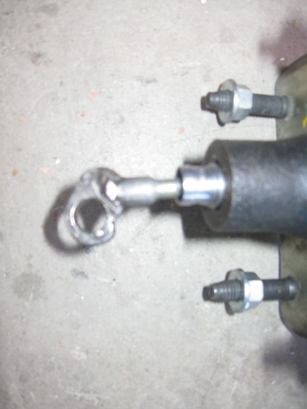
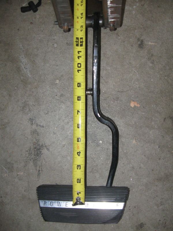
Right now the big deal is brakes. The existing brakes worked for a while but it had a bad habit of jamming full on. I blame that on how short of a booster pushrod I have:
Plans are to get a Tallon Hydraulic pushrod and put a rod end on the pedal so it will be much more tolerant of misalignment.
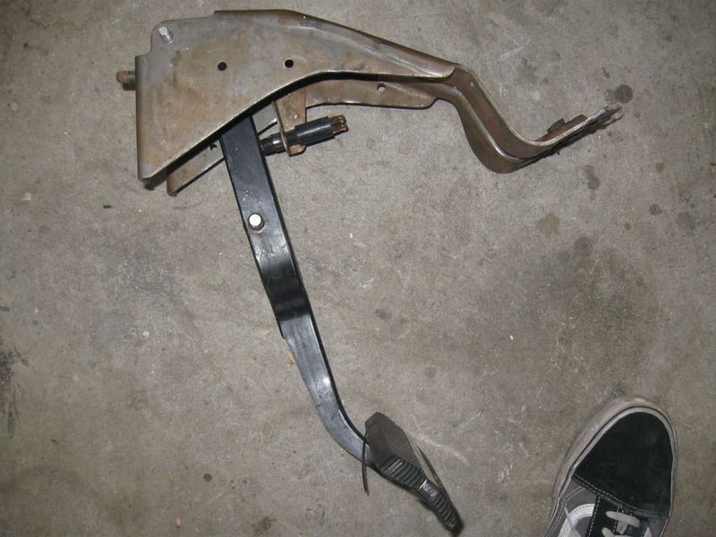
Speaking of pedal the stock ratio is lowsy, 2.5:1. Most literature I can find on GM power brakes have 3.5-6.0:1 ratio so the brake always felt spongy and weird. They'd grab but not lock the brakes. Here's the stock pedal assembly:
You can see how far from the pivot point the pin for the booster pushrod is. The pin is welded in place so I'm going to cut that out and press in a sleeve to get a 3/8in bolt in there since the Tallon pushrod is threaded for 3/8-24 and so is the rod end I have so I'll make that work. I'm also going to cut the pedal arm down by 2.5in to get a better 3.8:1 ratio and by moving the pivot point straight down I'll retain the same travel arc on the pedal so it won't try to "tuck under" at full travel.
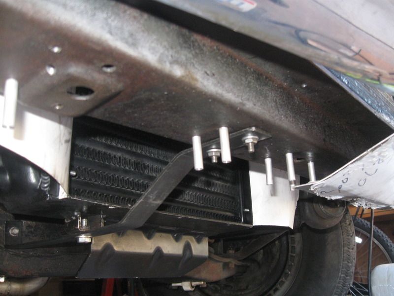
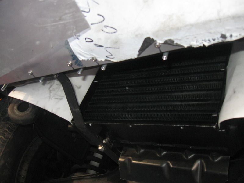
The biggest on going project has been to get the intercooler ducting complete. I'm trying to be stealthy and save cost by using a factory GN intercooler that mounts behind the radiator so the scoop goes under the radiator and the core support to duct air to the face of the intercooler. Here's some pictures of the work done so far.
Intercooler to fan gap, it's tight but the intercooler itself has a 3/4in deep recess between the frame you can see and the core to improve the transition. I have a panel being bent (my brake only goes up to 18in and the radiator core that it bolts to is 22in wide.
Pictures of how the plates bridge the gap between the lower valance and the bottom end of the core support. Those standoffs are 1in tall and give the air gap for part of the ducting. The gap between the bottom of the radiator and the core support is 1.5-1.75in depending on if you are on the front of the core support or the back.
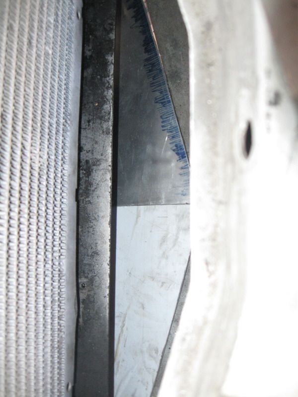
There's the intercooler and gap between the back of the front plates
That plate fits between the front ducting/scoop plates and the intercooler itself. The cut outs clear things like the intercooler mounting bracket, the inner fender splash sheilds, and the air dam on the bottom of the intercooler itself. I'm waiting on the top side duct before I make the side plates of the duct to seal it all up.
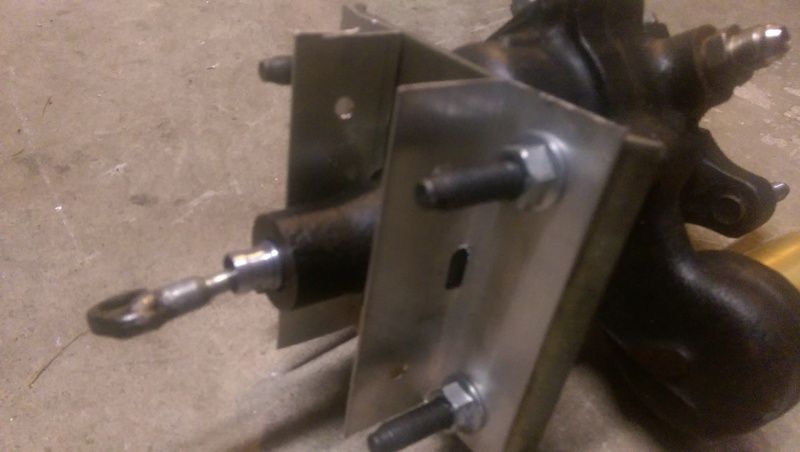
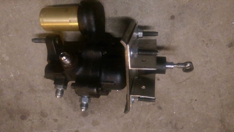
So Tuesday night I went out and machined up the pieces of the brake booster mount out of 1.5x1.5x0.060in aluminum 'L' channel. I decided to put the holes for the booster mounting bolts in the middle of the profile and as such... the nut in the center of the hydroboost that holds the booster to the mounting plate hit the channel no matter which way I did it. Wanting to mount it more like an I-beam I clamped a pair back up in the mill and used a 5/16in ball nose end mill to mill a relief in the bracket to clear the nut. A few tries and I had the right slight and the ball nose made a very nice looking radius to the cut. Got to use those more often.
I managed to bolt the brackets on the car and on the booster and then hold them apart and measure the gap so I could size the threaded pushrod from Tallon Hydraulics. They have the market cornered on those pushrods and I paid $17.52 to ship a blasted $15.00 pushrod! Hopefully this weekend I'll get to cut down the brake pedal and get it machined up for welding. I'm debating on what sort of joint I want to put in it instead of a straight butt joint when I weld the pieces back together. I think a step joint would be both simple and stronger, just do I step it front to back or side to side? Side to side would be easier as I don't have to file the corners square. Thoughts?
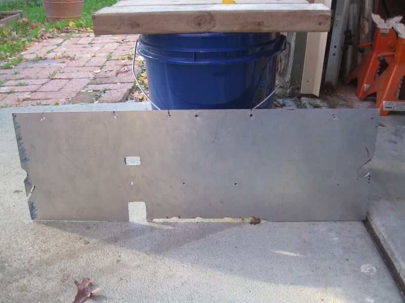
Sold my Tire Skates to my landlord for his Mini and used the proceeds to buy my caliper brackets from an online machine shop. $112.56 shipped for a pair of these in A36 steel:
They still need work to get to this:
Still most of that work is fairly easy, the only hard bit is getting that top left relief radius cut with a manual mill.
Last edited by CTX-SLPR; December 11, 2016, 10:09 PM.
Been working on the brakes this weekend and finished up, at least for the time being till I need swap the pedal rods, the mount for the booster and master cylinder.
The Al angle is a bit thinner than I would have liked honestly but there they are with those nice reliefs machined into them to clear the big nut. I might get adventurous and press out the super long stock studs and go for something shorter or just nut and bolts but I'll stick with them for now.
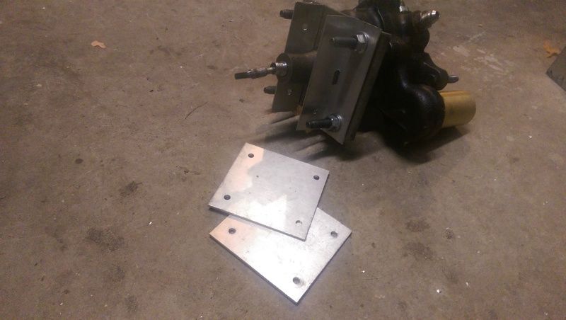
The plates that hold the booster angles together and space them 1in apart.
The receiving end of the brackets bolted to the firewall. There is another plate under the brackets that will hold the pushrod boot to seal up the hole through the firewall.
All bolted up straight. I was already concerned at this point how close the master cylinder mount got to the inner fender... When I put the master cylinder on there the rear line port was behind the inner fender so something had to change. I took those spacer side plates and moved one of the holes to angle the whole booster and master cylinder up around 8� then cut edge of the plate down to fit in the angles. Works a charm!
The reservoir cap isn't quite level but it's close. Both of the ports are well clear of the inner fender as well.
The washer reservoir sits right over the top of the booster so I will have to move it over and up ~3/8in to clear but it does clear the booster and the hood hinge while being almost unnoticeable different from stock.
Related because the engine oil dipstick hit the side of the master cylinder and was impossible to get out, I bent the tube up using the old MAP gas torch because it wouldn't fit in either of my benders with the tab welded to the side.
Used a bolt to keep the top bit straight and heated the bend cherry red and gently tapped it around. Probably need to swing it a bit more but its mostly there and the dispstick still slides in and out just fine.
Big update: It's running and driving but with issues. Namely I've got something wrong with the Range A sender either in the 4L80E or in the harness since I've got both out of range and performance error codes which means it's effectively disconnected. This I think is making it think it's in gear all the time and it does not like going from in gear to out of gear smoothly.
I also have had trouble with the timing tables, mainly the LC2 (Grand National Turbo6) has older style heads and needs more timing than even the NA L36 (3800 Series II) so I finally found a stock LC2 table tonight to start tuning off of with the 9psi wastegate spring.
Hopefully on Friday I'll get my beautiful and patient and not to mentioned patient assistant to video it rolling down the road by our house. I'll see if I can't get some of the rest of the cruise photos off of Facebook to show the turn out. I was pretty worn out last night from having put on my first Cruise-In with my church. We had ~30 cars and 140 people stop by, a great start for something we didn't do a whole lot of advertising for. Having bounce houses for the kids definately increased the turn out, more than one dadshowed up with a car and kid(s) and loved it.
I drove it to work today as well after the timing reflash it's a whole different car with much better road manners. Also have way more solid brakes, to the point if I get careless pushing the pedal down it'll lock the front right tire up! Need to balance the adjustments out on the front drums. More reinforcement that Buick Alfin drums are very very good brakes, even in a 4000lb car!
Big deal is that because it thinks it's in gear all the time, idling in the driveway and at a stoplight in gear basically mean the same thing so it pulls at the lights and spikes ~400rpm when you put it in park after a drive if you don't let it idle for a bit. I have got to get the range sensor fixed so it knows it's in gear and not so I can tune the two different tables for in gear and out of gear idle.
 Tweet
Tweet

Comment