-
Hmmm, with adding two more wheel speed sensors, you could build an MSGPIO and create your own ABS and traction control too! Don't know where you'd put yet another box though. -
I can't take credit for the idea. The guy who is doing fabrication and wiring on the LSR Charger Daytona da 'Geek has been tuning and wrenching on did it on that car and we copied the concept.Originally posted by TheSilverBuick View Post
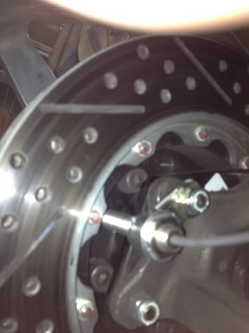
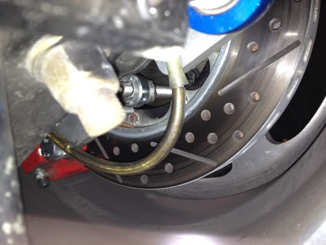
Funny story: I thought it might work well to read the signal off the 10 bolts that attach the rotor to the hat and after putting it in place and spinning it around we got nothing. So it suddenly dawns on us, are those fancy tri-wing fasteners steel? Nope they're non-ferous stainless, back to the 5 wheel studs which actually allows us to bury the sensor a bit more out of the way of road debris.Last edited by CDMBill; July 24, 2012, 02:38 PM.Leave a comment:
-
You dont need a glove box. Your big stang has all kinds of places yo store junk.
Cool to see it run again. And, hang out again.Last edited by Scott Liggett; July 24, 2012, 10:48 AM.Leave a comment:
-
Great write up Bill! I really really really really like using back of the stud or screw head for the wheel sensor.Leave a comment:
-
Well done! Great progress in a weekend. Sounds like the newest generation of MS is worth the price.Leave a comment:
-
The EFI update went well this weekend with Scott Clark aka DieselGeek coming out to cool temps in SoCal for the three day thrash.
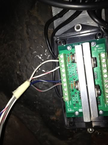
We made a completly new harness for the injectors, sensors, power supplies etc. This was to ensure a clean slate install after the last five years on the old set-up and to address a persistent issue with voltage spikes at WOT. The other reason is the MS3X supports sequential control over the injectors vs. the batch fire on the old unit and therefore the injector harness has to have eight individual trigger wires. The MS3X also has the ability to drive the 2 four tower watsed spark coils I currently run or eight individual coils which I will eventually transition to when we are ready for individual cylinder spark timing. The wasted spark coils require an out board Igniter and I have used this one form EFI Source for the last five years. It has four op-amps attcahed to massive heat sinks and has been trouble free. The two four tower coils are in essence two coils in each module and they draw 20 amps each.
The other major issue we had to address is that the MS3X is set up natively to drive high impedance low current OEM type injectors in sequential mode, but not the higher current RCI low impedance 96 lb/hr peak and hold injectors I currently have on the car. That meant either getting 8 new high impedance injectors or finding a device to provide additional current and the ability to lessen the 'deadtime' on the RCI's. New high flow injectors high Z injectors would run well over $1000 so we went bloack box device route for $269 which is the VersaFueler from Acceleronics.
The VersaFueler is wired in series between the ECU and the injectors. We directly wired the injector outputs from the ECU harness using new high tech crimp/heat shrink/glued butt connectors. I know you are thinking "butt connectors?" are these guys idiots? Interestingly the thinking on making these connections has evolved and the high end engine managment systems like MOTEC and McLaren specifically prohibit doing the old solder and shrink wrap approach. So using the fancy. $.25 apiece butt connectors with a Klein crimping tool and a heat gun we went to work. Where the harness goes through the firewall we used older GM WeatherPak style connectors. These things are a PITA too but the MSD crimping tool I bought about ten years ago really helps make them secure.
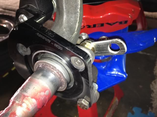
We added the tooth gear reading wheel speed sensors which are US made Cherry P/N CH414N from DigiKey to the passenger fornt and back wheel. They read the wheel studs off the back side of the hub and the axle respectively which keeps them out of harms way as much as possible as well as making the senosr mount fabrication really easy.
For sequential EFI you also have to add a cam postion sensor. We used the same Cherry sensor and fabbed up a mount so that it would read a tab we bolted to the cam gear on the belt drive. We learned the hard way that the tab needs to be made of pretty stout material as the first one broke off during the first WOT test. The second tab is cut from a scrap piece of 1x1x.125 angle iron.
Even more interesting was that when the first tab failed the ECM switched over also seamlessly to semi-sequential mode while we were going about 85 on the test course aka the toll road allowing us to drive home. We had done a slower pull up to around 130 without incident but the acceleration rate at WOT was the difference. The analytics in the MS3X are awseome as we could see the 36-1 trigger wheel signal was still on the laptop screen, but the once in 720* cam sensor signal had disappeared. Fortunatly the tab didn't take anything with it when it left the engine compartment.
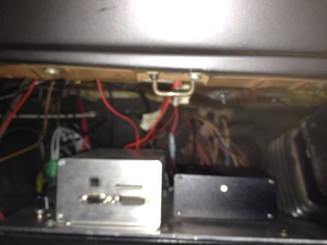
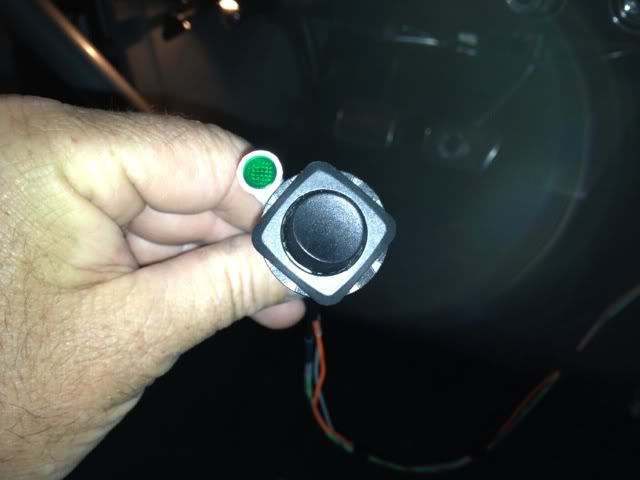
The other really neat addtion in the MS3X is the SD card datalogging feature. The ECU has a card slot in front next to the USB port (sorry for the crap picture) and offers the ability to start and stop the datalogging with a simple momentary switch. It will also drive an LED which pulses when you are successfully in datalogging mode and then blinks quickly to confirm the end of the log. We made a little extension harness as I wasn't yet sure where to mount the button and the LED. I was able to log all three test runs at Irwindale Saturday night without having to have the laptop in the car. Between rounds we reviewed the logs, compared notes on hwat we saw and heard and made tuning adjustmenrts.
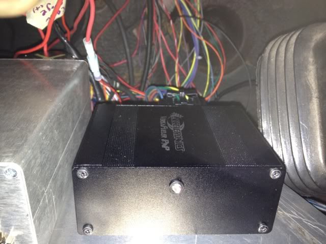
I sacrificed my glove compartment to house the MS3X, the VersaFueler box and to have a place to mount the external MAP sensor we are using to measure crankcase vacuum as well as the relays and wiring busses for ground, 5V+ and 12V+ that are on the underside of the mounting plate. This alsp makes connecting the laptop easy, aswell as accessing the SD card and the other ports on the ECU. The harness is long enough so the mounting palte can be pulled out for service or testing if/when something fails.
The best part of this was that the car started on the first try and other than running out of gas while doing the initial tune and having to coast nto a gas station we had no issues. The mysterious voltage spikes that had caused trouble before are gome and I attribute this to having the ECU and sensors on a complety isolated circuit form all the nosisy stuff like injectors, injector drivers, coil drivers, coils, fans, pumps etc.Last edited by CDMBill; July 24, 2012, 10:16 AM.Leave a comment:
-
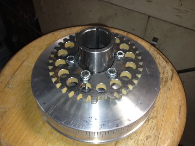
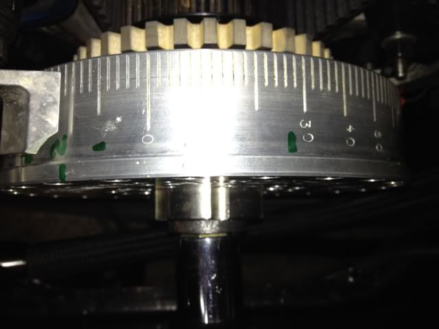
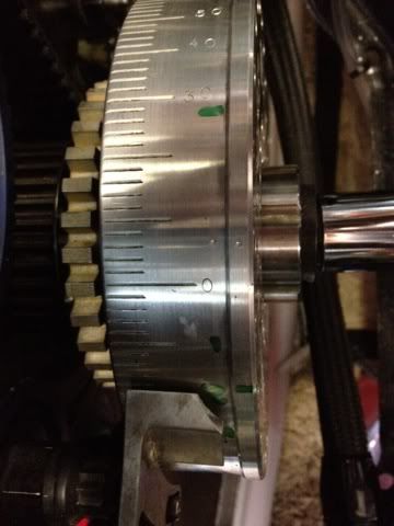
The trigger wheel (EDIS) project has turned out well. Assembled on the Innovators West damper the wheel looks like this
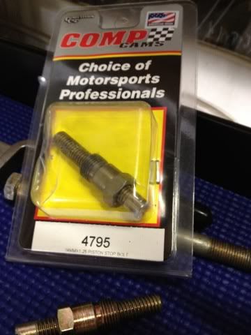
With the damper installed back on the crank snout I needed to re-set the timing pointer so I could then verify the timing in the EMS with the actual timing based on the spark event. I used a Comp Cams Piston stop tool to mark the damper on both sides of TDC. As the picture shows the stop points were not at the same number of degrees on either side of 0 or TDC on the damper as indicated by the timing pointer. It had been knocked completely out of place by one of the disintegrating P/S belts earlier in the year. It been moved by about 6 degrees. With the pointer aligned, I pre-oiled the motor by spinning the external oil pump, reinstalled all the pulleys and belts and radiator etc. and I fired up the car. It started just fine and after warm-up settled in at idle. I used my ancient CalComp timing light to check the actual timing vs. the 26* I have in the EMS. It showed 30 on the damper under the light.
To adjust for that you change a value known as trigger angle in the software. The EDIS wheel is known as a 36-1 wheel meaning it has 35 teeth and a missing tooth. (you can see the missing tooth location in the first picture) When the sensor sees the skip that tells the EMS where it is relative to TDC so it can tell the coils to fire at the right time. There is no distributor so the only place the psark jumps a gap is at the plug. My wheel is set to have the missing tooth approximatly 7 teeth before TDC and is located at rough 7 o'clock because of the sensor location which is at roughly 4 o'clock.
It was set at 64* degrees previously with the old trigger wheel assembly. To retard the initial timing I added four degrees to the trigger angle to a total of 68* and the timing showed that I now had 26 degrees intital on the damper matching the value in the software timing map.
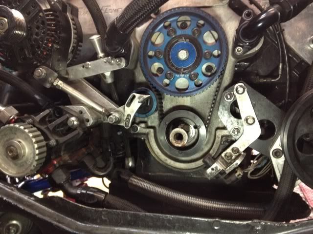
The pivot arm I fabricated for the GM LS1 sensor allows me to easily set the air gap, mine is set to .029", between the rotating EDIS wheel and the sensor while keeping the relationship between the sensor and the wheel perpendicular.Last edited by CDMBill; July 16, 2012, 01:40 PM.Leave a comment:
-
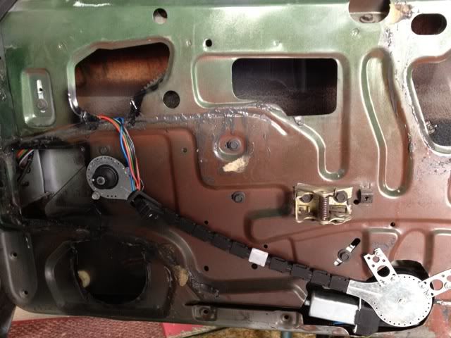
This will give you an idea about the Electric Life Colibri kit. Its essentially a fully contained worm driven cog belt that engages the factory mechanical window crank mechanism. The kit cost $140.00 for the two big windows and three switches and all wring and hardware.
I only found one true direct replacement set-up for the 71 Mustang and it was $700. Original factory stuff on eBay goes for over a grand and the weight is crazy heavy.
Randall, you may have better luck finding a complete electric replacement kit as there is a better selcetion out there for GM stuff. That would solve your decrepit mechanical window situation. Expect to pay about $300-400 from what I saw around. I'll pst a few more pictures later.
Leave a comment:
-
My cheap little 110 flux core mig welder is made in italy - I got it well used and it's done everything I've asked of it for several rolls of wire, maybe my ancestors over there have a good grasp on controlling those damned little electrons.Leave a comment:
-
Pictures? I want to convert the Skylark over to electric. The regulator on the manual crank is about wore out on it and I'm expecting it to go in the next couple years.Leave a comment:
-
Lamest project so far
I got into the wiring today and while I was tearing everything open I thought I'd go ahead and put in the power windows. Yes, power windows. If you've ever got stuck in staging all belted in the two layer suit sweltering with sweat coming out of the helmet, you may understand.
The weight is a push with the dead speakers I took out, so I'm calling it good. The kit is pleasant surprise so far in terms of installation. I did the passenger side which was the crucial one for me I'll finish the drivers side this week.
I did a quick test and the window goes up and smoothly. The kit is a universal setup from Electric Life called Colibri and is made in Italy!?Leave a comment:
-
No kidding, there is always that nagging feeling that there might have been some damage I missed.Leave a comment:
Leave a comment: