Announcement

Collapse
No announcement yet.

Drag Week 2012 - Project GIRTST 71 Mustang (get it right the second time)

Collapse
X
 
  • Filter
  • Time
  • Show
Clear All
new posts

  • #16
    Thanks for the nice words. Mustang Project has an interesting LED part they sell for the 67/68 louvered hood turn signal. But I thought I'd go the modified route with bulbs as they also offer an LED bulb replacement and I keep the convetional wiring and connections.

    I have set of their tail lamp/brake lamps still in the box from 2010 as I never seem to get to those aspects of the project. This year for sure. That and the fender I need to replce and the racing hood painted and and and.
    Drag Week 2006 & 2012 - Winner Street Race Big Block Naturally Aspirated - R/U 2007 Broke DW '05 and Drag Weekend '15 Coincidence?

    Comment


    • #17
      Ive got Grumpys calender hanging up in the basement.

      Comment


      • #18
        Me too in the garage.
        Drag Week 2006 & 2012 - Winner Street Race Big Block Naturally Aspirated - R/U 2007 Broke DW '05 and Drag Weekend '15 Coincidence?

        Comment


        • #19
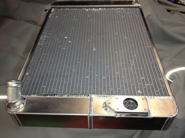
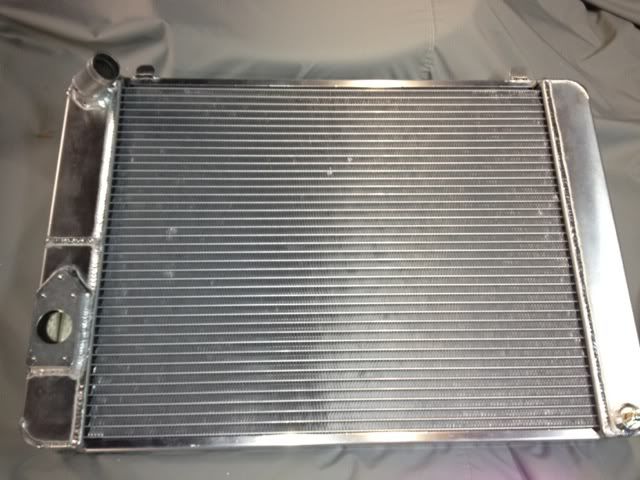
          With the new radiator from AFCO in hand and finally some free time to work on the car I've made some progress. The new radiator is a dual pass unit with a 45* top inlet and wleded in adaptor for the Mezeire 55 GPM pump. The radiator was ordered per my specs so it was good to measure three times and order once.


          A dual pass radiator runs the coolant across the top half of the radiator and then the coolant flows down the tank on the opposite side and out to the pump. Dual pass radiators more effectively utilize the entire core of the radiator which is helpful with an almost square core such as I have room for in the core support. However, dual pass radiators require more pump volume to over come the restriction inherent in asking the coolant to make an additional 180* turn. To minimize the increase in restriction the tanks on a dual pass are often wider than normal which you see here. The horizontal weld in the middle of the tank is where the divider is located


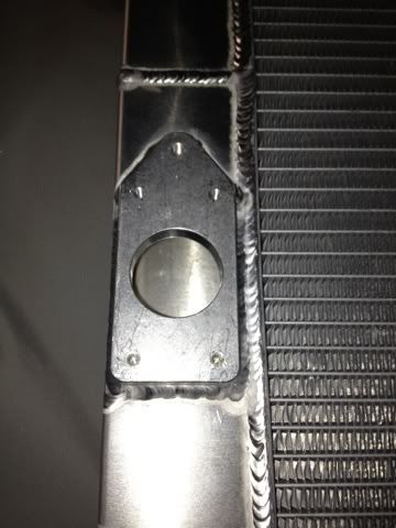
          The adaptor was welded on by the AFCO crew in the location I specified so it wouldn't hit the cross member it sits just above.


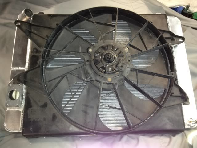
          Before attaching the water pump I test fit the fan/shroud combination. The fan is the Linclon Mark VIII unit that purportedly pulls 4300 CFM. All I know is that it draws a lot of current, a 70 Amp relay is recomended, and I'm using a 100 Amp unit that looks like a starter relay as I partly melted a 70 Amp relay back during the two days of down pour we had at Drag Week in '06. The fans run about $45 used on Ebay.

          Fortunatly, the fits just as it should as I allowed a bit of extra space on the inlet side so the the inlet and the pump will clear the shroud and not require additional surgery. I'll cover that gap with a piece of plastic from another fan housing.


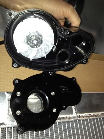
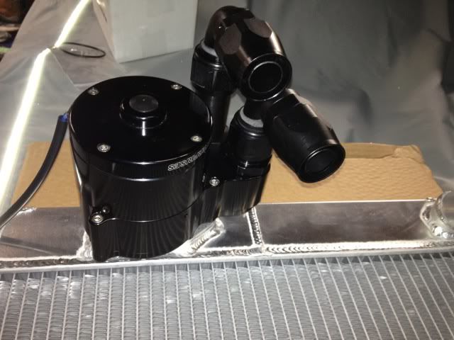
          The Mezeire pump mounts to the welded in adaptor which came as part of the complete pump kit. After placing the supplied o-ring in the CNC milled flange, four bolts attach the pump backing plate to the radaitor. Then pump body itself is bolted on with five more socket head cap screws.


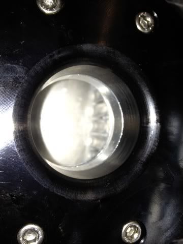
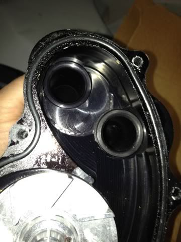
          The interior of the pump is as much a work of art as the exterior and the two AN16 adaptors screw into housing leaving a smooth transition for the coolant flow.


          With the pump body attached and the AN 16 adaptors in place along with two Earl's Ano-tuff 90* swivel fittings, I'm ready to look more closely at line routing.

          Drag Week 2006 & 2012 - Winner Street Race Big Block Naturally Aspirated - R/U 2007 Broke DW '05 and Drag Weekend '15 Coincidence?

          Comment


          • #20
            AFCO ships each radiator in huge box with injected foam at each corner to protect it during shipment. For additonal protection the core is wrapped with a cut to fit cardboard shield. I'm keeping it in place during all of the test fitting. I'm keeping track of the .25" or so it adds to the thickness of the core during mock up.

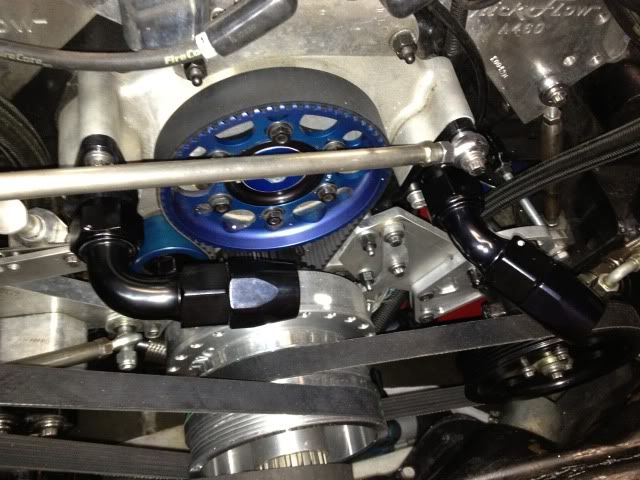
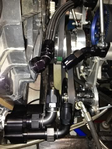
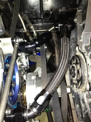
            With the radiator and fan sitting sitting on the lower core support and held in place with plastic jawed cabinet makers wood clamp I can finally see exactly where the pump outlet fittings are located relative to the inlet fittings on the belt drive cover. Note the size of the 45* and 90* fittings you see below.


            With everything in place the remaining space gets a bit snug.


            After the Drag Week 2011 over heating fiasco I want to leave as little to chance as possible. Because this car is one big compromise for street, drags, standing mile, autocross and road course, I'm trying to be sure I have more than enough cooling capacity, and that everything will stay in place under extreme circumstances. One of those circumstances we learned the hard way last year is tossing a belt. Therefore I'm trying to keep the coolant hoses away from the direct rotating path of the belts as possible.


            As a belt comes apart the non-tension side seems to whip the most. I base this conclusion by observation of what got beat up by the power steering and alternator belts that the motor tossed last year during the first day of competition.

            I mentioned the sizes fo the fittings earlier. Until everything is in place you can nver be completly sure of where the hose routing will be best. The other issue is that #16 AN line doesn't have a very tight bend radius so all bends have to be gentle. With the location of the two pump outlets there has to be a stagger in the length of the #16 adaptors so you can get a wrench on each fitting. Mezeire supplies these separately so you can miz and match as needed.

            To keep the hoses away from the belts as best as possible the drivers side will be very short and the passenger side will go up and over it. Because I woory too much about even cooling bank to bank, I try to keep the number and amount of bends in the lines the same. As it runs out I needed to run 45* at the engine side and 90*'s on the pump side. So far so good. But, the fitings in the first photo on the fornt dress are Summit brand. Right before Christmas thay had a screaming deal on these for $18 each. Based on my earlier mock up I thought I needed one more 90* and one more 45* so that's what I ordered. They came and they looked surprizingly good. But they are huge compared to the Earl's 45* I already had on hand meaning they are almost an inch longer. Doesn't sound like much does it, but in tight confines it can means a no go. Once I realized that, I had to bite the bullet and buy two more Earl's 90* swivel fittings, $49 each, ouch. With the Earl's Nylon braided I'm using I've found that the fittings brand match isn't quite so crucial, not to mention is way lighter and is much easier to fabricate. #16 braided stainless is almost complelely inflexible under one foot in length. I have kept my oil pump inlet line stainless because its critical that it not fail and its low down in front of the oil pan and less likley to get cut by trash on the freeway. Final fitment of the lines comes next and then the final radiator and fan mounts and then finally the oil and trans coolers.
            Drag Week 2006 & 2012 - Winner Street Race Big Block Naturally Aspirated - R/U 2007 Broke DW '05 and Drag Weekend '15 Coincidence?

            Comment


            • #21
              Bill
              fabulous work.

              Have you found new bulbs for your sectioned grille lights? I would not use conventional bulbs anymore - now that you've moved the bulbs much closer to the lens - I'm afraid the heat generated by the bulb would melt the lens. I hope you can find an LED replacement that will generate zero heat and not melt those hard to find OEM lenses from '71.

              Super hi-tech stuff you're doing to this car, never seen a water pump set up like that.
              There's always something new to learn.

              Comment


              • #22
                Bill, not to hi-jack your tech thread with the Aeromotive and Jet Hot questions, are you running a separate fuel solenoid for the N2O? I "thought" you've said your injectors were big enough to cover the N2O hit, or if not why not an upstream staged set of injectors?
                Escaped on a technicality.

                Comment


                • #23
                  Randal, the old induction setup was a single four barrel throttle body with N2O only fogger nozzles and a plan to run dry shots with enrichment from the injectors so your memory is correct that the injectors were/are are sized for up to 1200 HP EFI N/A and EFI dry shot enrichment combined.


                  Two problems emerged as I looked at actually spraying the car. Early N2O dyno testing pre EFI with a Zex plate and a 150 shot killed the original converter I bought with the Strip terminator AOD. Turns out 800 ft./lbs. was the limit. Scoot and Chad were there when we made that little oops. Funny thing we had made a bunch of N/A pulls tuning for DW '06 and thought we'd try the spray.

                  We couldn't figure out why we barely moved the needle on rear wheel HP. It drove hoem normally and fugured we's look at the N2O tune later. Driving it to the Car Craft anti-tour the next weekend the tranny went into thermal hari'kari and would no longer move the car forward. So a couple grand later I have a rebuilt trans and a Lentech converter good for 1500 ft./lbs. it stalled at 2600 N/a at DW '07. Damn!

                  Next converter from Edge solved N/A stall issue. In the mean time the on-the-edge traction situation had me questioning the benefit of an all or nothing shot which you are stuck with in this type of dry system. So it never was used in anger on the track.

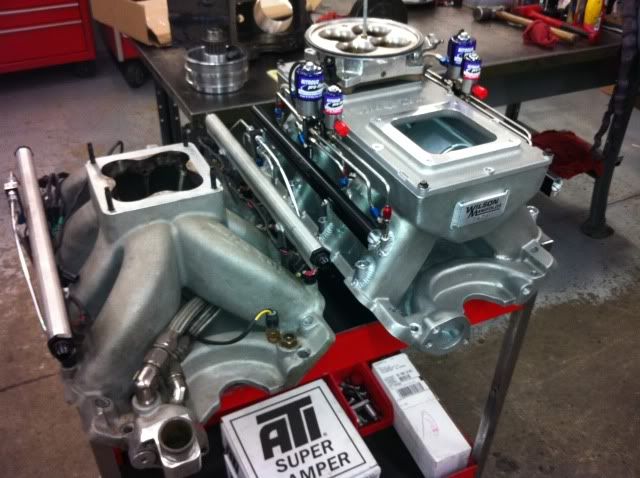
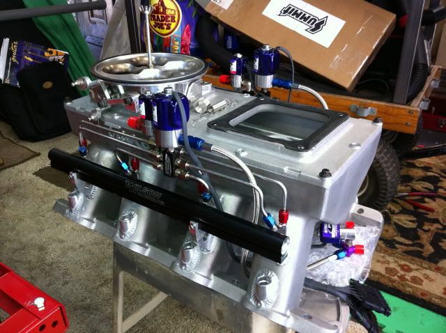
                  Fast forward to the last second rebuild for DW 11. I figured (and this always costs me) as long as the manifold was being ported and set up for the fuel bungs and rails at Wislon Manifolds, why not go ahead and get a wet system plumbed at the same time so it could be optimized as best as possible for both an N/A and sprayed configurations? So I did. I knew I needed to able to run a progressive set up as well for traction and launch reasons so the system is set up for that too with Wilson's new Progressive controller. I'll be writing that up and testing later this Spring when I get the fuel system questions resolved.

                  So the new deal looks like this:


                  We couldn't put the injectors as high up in the runners as would be ideal for N/A only, but I gain and advantage in part throttle response and tunability which is great for street manners, autocross and open track stuff.

                  And, later when we do spray it, the location of the fogger nozzles will complement the EFI instead of buggering the distribution had they been reversed. i relied on the Wilson engineers for this set of decisons and I can say with confidence the EFI tunability side has been great and we made decent power.

                  Last edited by CDMBill; February 2, 2012, 03:40 PM.
                  Drag Week 2006 & 2012 - Winner Street Race Big Block Naturally Aspirated - R/U 2007 Broke DW '05 and Drag Weekend '15 Coincidence?

                  Comment


                  • #24
                    Killer write-up, Bill. That manifold setup with the injection and N2O is pure sex. I look forward to seeing more!

                    Regarding the issue of tossed belts taking out hoses: have you thought about adding a small shield around the pulleys for peace of mind?

                    Comment


                    • #25
                      Darren it's a good question. I have thought about it and that may be the right approach until I'm sure I've fixed the belt issue. I've reworked the accessory mounts so fingers crossed.
                      Drag Week 2006 & 2012 - Winner Street Race Big Block Naturally Aspirated - R/U 2007 Broke DW '05 and Drag Weekend '15 Coincidence?

                      Comment


                      • #26
                        Ah, so it's a progressive shot you're looking for, and I see how the fuel and N20 lines mix in one nozzle which I could see having a better distribution.
                        Escaped on a technicality.

                        Comment


                        • #27
                          That manifold is the thing that dreams are made of... pure beauty!
                          Why think when you can be doing something fruitful?

                          Comment


                          • #28
                            Wow cool stuff Bill! I had never seen that waterpump setup either. I can only dream of that horsepower level right now but I like how you're planning ahead. Steve with the Pro Charged Blazer did a lot of careful planning and it really helped his setup.

                            On the blinkers, have you thought of using fiberglass? You can use the old stereo installer trick of grill cloth to create your form and then glass over it and finish with a little filler if you need to. You can make it removable by extending the top/bottom so that the new addition simply screws to the original housing. I've done it before and you can create some really cool shapes with it. I used epoxy resin rather than polyester. To better explain the process, I found a good set of install pix online.

                            The first picture is the form and another with the grill cloth stretched over the form, then you apply resin to the grill cloth and let it dry, then lay some glass with more resin, and finally finish with filler before painting.

                            Click image for larger version

Name:	1 housing and grill cloth smaller.jpg
Views:	1
Size:	28.6 KB
ID:	860074Click image for larger version

Name:	3 grill cloth with resin smaller.jpg
Views:	1
Size:	25.1 KB
ID:	860072Click image for larger version

Name:	2 grill cloth with fiberglass smaller.jpg
Views:	1
Size:	27.3 KB
ID:	860073Click image for larger version

Name:	4 housing with filler smaller.jpg
Views:	1
Size:	25.9 KB
ID:	860075

                            here's the posting I grabbed the pix from

                            http://www.fiberglassforums.com/audi...7-drivers.html
                            Last edited by Dignlif; February 3, 2012, 12:31 PM.
                            Rich

                            Drag Week Survivor 2009, 2011, 2012, 2013 - 2nd Place - Pro Street N/A, 2017

                            Comment


                            • #29
                              Rich, that's a good idea. I've been thinking about ways to mount the bulb somewhat sideways but still use the same mounting flange for the bulb holder. I have some fiberglass repair material for surf boards that cures with sunlight although I'm not sure that is right for this kind pf work. Per Milner's suggestion I have foundsome LED replacement bulbs. I'm going to get a small sheet of plastic to work on the carved up housing. Any idea what kind of plastic these things were made of, and what kind of glue I should use?
                              Drag Week 2006 & 2012 - Winner Street Race Big Block Naturally Aspirated - R/U 2007 Broke DW '05 and Drag Weekend '15 Coincidence?

                              Comment


                              • #30
                                I would think a two-part epoxy type adhesive would be strong enough, especially if you inlaid another material spanning across the two pieces like thin/ narrow aluminum strips. Setting up the angle with just plastics you could cut tow triangular pieces at the angle you want and support the socket with those, then create the other 2-3 pieces per side and epoxy it all together. With LED's is should be bright enough but you can always go back and install some aluminized tape or aluminum foil? to create an internal reflection.

                                I found this cool article at West Systems about bonding plastics. Looks like their product is about $20 for an 8 oz kit, 4 oz of each part. Could be worth a try for experimenting.
                                http://www.westsystem.com/ss/gluing-...-g-flex-epoxy/

                                For an angle with the grill cloth/ fiberglass method all you'd have to do is use the same two pieces of angled plastic from above and glue the 3 pieces to the base, then stretch the cloth to cover all the openings. I forgot that the reflector base comes apart from the lens housing so you can attach the angles and receiver permanently to the base with this method.

                                We did a bulb angle rework on my tail lights once to gain some room for woofer enclosures (yeah I know but it was the 90's and I didn't know any better) and it worked fine.
                                Rich

                                Drag Week Survivor 2009, 2011, 2012, 2013 - 2nd Place - Pro Street N/A, 2017

                                Comment

                                Working...
                                X