Announcement

Collapse
No announcement yet.

The Silver Buick's 1969 Firebird OHC six project.

Collapse
X
 
  • Filter
  • Time
  • Show
Clear All
new posts

  • It's pretty easy. I start with the pics on my desktop (no clue how to do it otherwise). Then write what you want and "GO ADVANCED". You'll see a box to manage attachments - click that. It'll put up a box that allows you to browse. I put my pics on my desktop in folders so it's easy from there. Once the pics are selected hit post at the top of the browse screen. It'll take a while for them to load. When done hit the close box at the bottom of the browse screen. You're done!

    Dan

    Comment


    • Paul, I sent you a private message (PM) on uploading or linking pictures. Or you can e-mail them to me
      Escaped on a technicality.

      Comment


      • Thank you, Dan. I went that way but got a strange unuseable result. Sent the pix to SB and he'll make it right, I'm sure.

        Paul

        Comment


        • i always thought these engines were way ahead of their time!! i really like this project and think it's cool
          saw this on E-bay for anyone interested in a similar project...http://www.ebay.com/itm/Pontiac-OHC-...6615d7&vxp=mtr
          Patrick & Tammy
          - Long Haulin' 2008, 2009, 2010, 2011, 2012, 2014...Addicting isn't it...??

          Comment


          • Originally posted by Paul S View Post
            Good Afternoon Gents:

            Sorry for the delay. You can get the flu even having had the flue shot, OBTW!

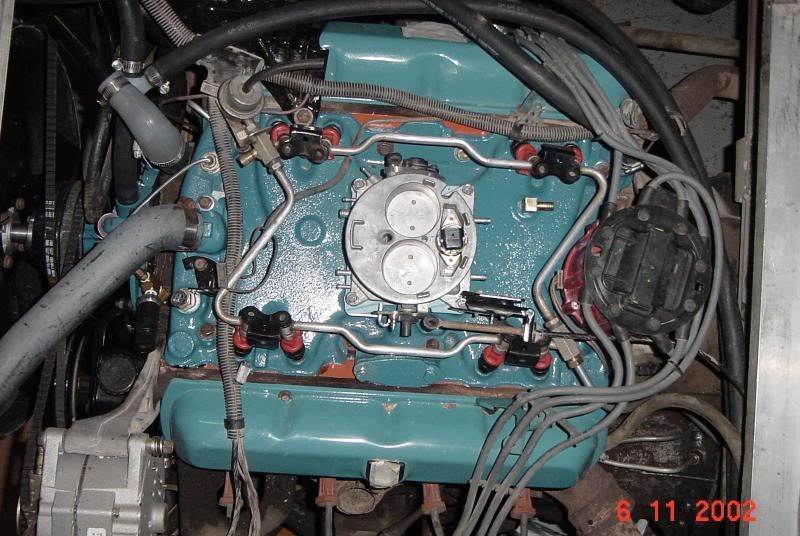
            The first, "Wide View-Front End of Rail" is a wide view with the Throttle
            Body on the right and the red and blue AN fuel fitting that is the fuel
            inflow line to the fuel rail. The Coolant Outlet is seen on the left, as
            well.


            The second, "Fuel Rail-Front Cylinders" is just a slightly closer view.


            The third, "End of Rail-Inj#1" is the 'money shot, as they say. The red and
            blue fuel inlet fitting, the end of the fuel rail, the fuel rail support
            pedastal and the #1 fuel injector can be seen. The clearance between the
            lower coolant outlet fitting bolt and the fuel right angle AN fitting is
            closer than I'd like but it works. There has been no interference issue, so
            far, even in removing the outlet for a gasket change. I could shorten the
            rail a tad, of course.


            OK, Guys, here's the thing. I have not figured how to add these pix to this reply. Two ways to go: 1) educate me or, 2) send me an email and I'll forward them.

            Sorry, Guys...

            Paul
            Thanks for the pictures Paul! I think I've got them inserted in the quote in the right order.

            I am thinking of doing rails with injector pairs and steel line between them if I can not get a straight line on the injectors.


            Some casual mock up I've done. I think you were able to lay over the rail more than my mock ups because the narrowness of the aftermarket throttle body.


            Got the idea about steel lines between the rails from the EFI Olds engine from the 70's.
            Escaped on a technicality.

            Comment


            • Thanks for posting the pix, Randal. The last one looks better if not so over expanded in its native form.

              Your idea using the steel lines is a good one. One thing that contributed to the tight clearance, in my case, was the inlet fitting on the end of the rail. There are solutions to that, of course. I got lucky, actually, that I got away with what I manufactured...

              Comment


              • What is the story on the hard lines as fuel rails?
                Whiskey for my men ... and beer for their horses!

                Comment


                • Originally posted by Bamfster View Post
                  What is the story on the hard lines as fuel rails?
                  What do you mean? On the Oldsmobile engine? That's how they came from GM. Early experimentation in EFI I guess before they decided on a hard straight rail that is less likely to crack and leak.
                  Escaped on a technicality.

                  Comment


                  • "hard lines" are standard issue on mechanical diesels - they're thicker wall than standard store bought fuel lines though.
                    There's always something new to learn.

                    Comment


                    • The '70s Olds ones are paper thin. The Seville I pulled all the brake parts and rear axle off of had the EFI Old's engine and I tried grabbing the fuel rail and stuff and it all just turned into a twisted broken mess in my hands as I tried to disassemble it.
                      Escaped on a technicality.

                      Comment


                      • Originally posted by TheSilverBuick View Post
                        Got the idea about steel lines between the rails from the EFI Olds engine from the 70's.
                        I now see why you also got the idea that the injector pairs on the OHC would have to be angled relative to the manifold runner center line. On the OHC, they don't - as I am sure you've seen already.

                        On Paul's set up, conventional practicality kicks in. It seems like the most feasible place to run the inlet to the fuel rail is at one end of the rail or the other. As you can appreciate, it can enter the fuel rail anywhere - middle, end or half way in-between, and at any convenient angle.

                        Comment


                        • Originally posted by OHC 6 Sprint View Post
                          I now see why you also got the idea that the injector pairs on the OHC would have to be angled relative to the manifold runner center line. On the OHC, they don't - as I am sure you've seen already.

                          On Paul's set up, conventional practicality kicks in. It seems like the most feasible place to run the inlet to the fuel rail is at one end of the rail or the other. As you can appreciate, it can enter the fuel rail anywhere - middle, end or half way in-between, and at any convenient angle.
                          I should note: While it may not be apparent from the pix, the injectors are inclined from the vertical so as to have their spray enter the port and impinge on the back of the valve, in so far as is possible. Of course, the MEFI2 is a batch fired system so the fuel 'parks' in the port for a time. I have a sequential system waiting in the wings, however...

                          As to how to plumb the rail, my first concern, in laying out the inlet at one end and the outlet to the regulator at the other, was to keep the fuel in the rail as cool as possible-cleanly 'flushing' the warmed fuel into the return. While I played with other arrangements, I wondered if at idle, in traffic on a hot day whether 'hot' fuel could be sequestered in the rail and raise havoc with the local AFR.

                          Paul

                          Comment


                          • I've never heard of that efi Olds. Interesting.

                            As Silver Bullet said these engines were ahead of their time. People who wanted economy bought the standard L6. People who wanted power got the V8. This one was stuck.in the middle appealing to techy types of the time or the ones who wanted a fancy european car. Small demographic. I wonder how much more popular this engine would've been if it survived to the gas crisis in '73.
                            BS'er formally known as Rebeldryver

                            Resident Instigator

                            sigpic

                            Comment


                            • Originally posted by Paul S View Post
                              I should note: While it may not be apparent from the pix, the injectors are inclined from the vertical so as to have their spray enter the port and impinge on the back of the valve, in so far as is possible. Of course, the MEFI2 is a batch fired system so the fuel 'parks' in the port for a time. I have a sequential system waiting in the wings, however...Paul
                              Yes, the inclination angle is clear and necessary. In the picture of the Olds engine, the injector pairs are splayed toward one another. If you put the nozzle centerline on the PORT centerline on the OHC, you'd have the same problem. But if you line up the nozzle centerline with the valve centerline, not on the port center, the injectors can be parallel. This is a very important feature for TSB since his rail fabrication would be a LOT easier if he can drill without the compound angle.

                              I was recently educated that with the sequential system and the right interface, you can tune AFR at each cylinder.

                              Comment


                              • Originally posted by Scott Liggett View Post
                                I've never heard of that efi Olds. Interesting.

                                As Silver Bullet said these engines were ahead of their time. People who wanted economy bought the standard L6. People who wanted power got the V8. This one was stuck.in the middle appealing to techy types of the time or the ones who wanted a fancy european car. Small demographic. I wonder how much more popular this engine would've been if it survived to the gas crisis in '73.
                                Unfortunately, Pontiac had to kill in at the end of '69 because the timing belt pulley would not fit under the hood of the second gen Firebird without a serious bulge in the bonnet. The stylists caused its demise.

                                It was very well ahead of its time and, yes, it was featured to a far-too-small demographic. TSB has done a great job of unearthing the historical content about the features that made it revolutionary, the most important of which is the fiber-glass reinforced rubber timing belt.

                                Comment

                                Working...
                                X