 Tweet
Tweet
Originally posted by oletrux4evr
View Post
-
I like this place as it seems those here drive their seasonal or hobby cars . I find driving more fun than staring at them . -
I find myself staring at my junk more frequently lately. I am not sure if I am wondering what to do about what ever my current issue is or pondering how I got to where I am.Originally posted by Eric View Post
Comment
-
Eric, just as a side note, this hood goes on a 51 Ford F7 with a roll back body. The owner uses it so he can take more than one vehicle to the shows... Although everything he owns is driven..
Didn't notice you were from Brazil, thanks for following along!
The TIG is used to fully weld the patches in place...
Front side:
Back side, full penetration on the weld..
The weld seams are then planished and dressed. Next, the front of the hood had a stress crack adjacent to one of the rubber bumpers. To stabilize the hood prior to cutting out this area, the brace is clamped back in place..
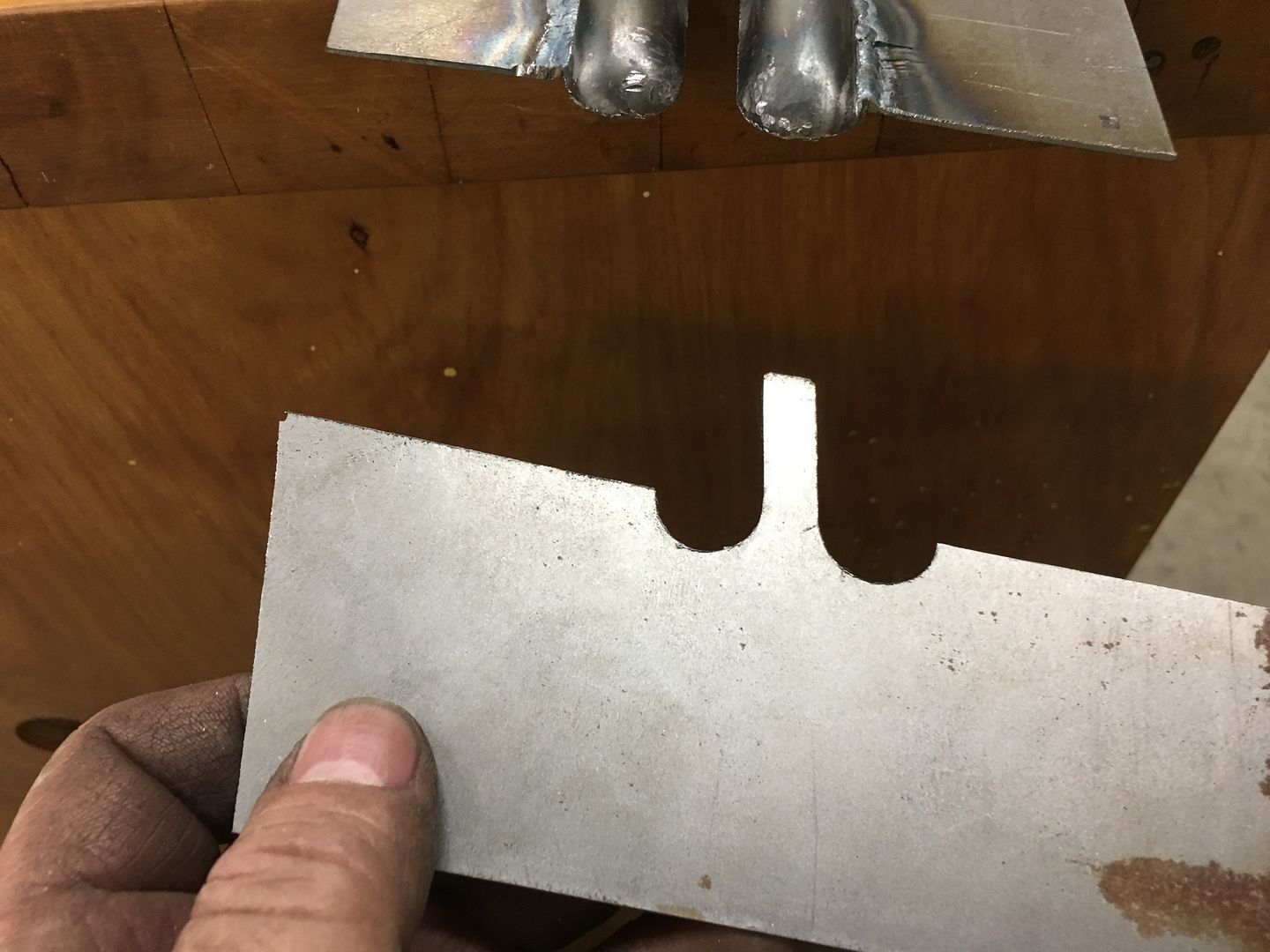
The damaged area is cut out, a "doubler" had been used toward the front to add strength to the area, so care is used to not cut that off..
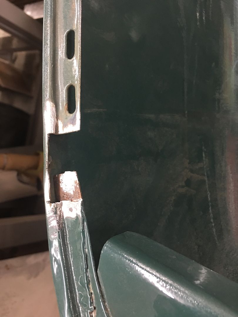
A replacement patch is cut out, bends added, and tacked in place. A plug weld ties this in with the doubler..
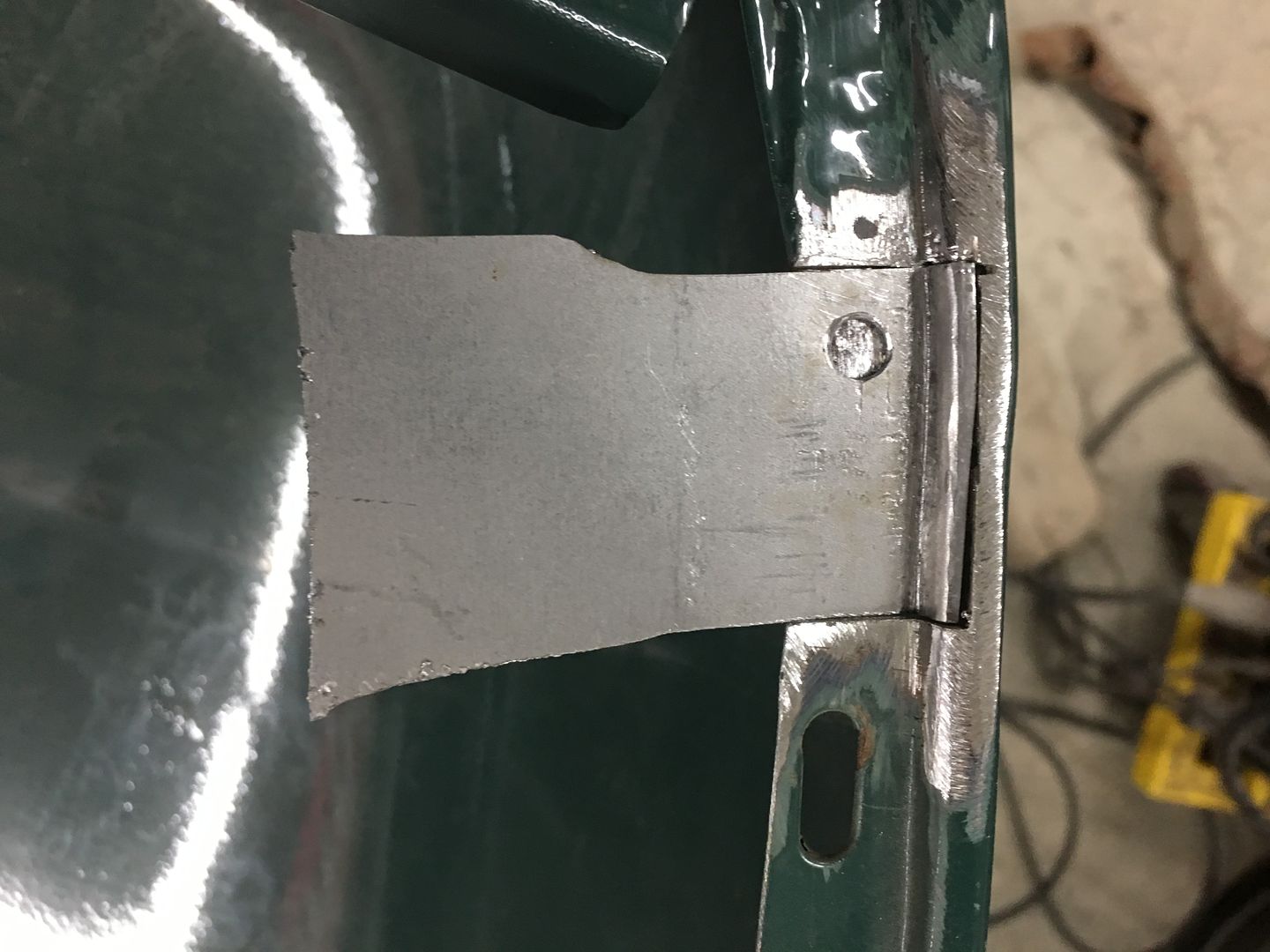
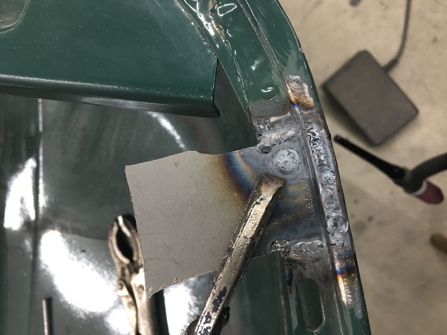
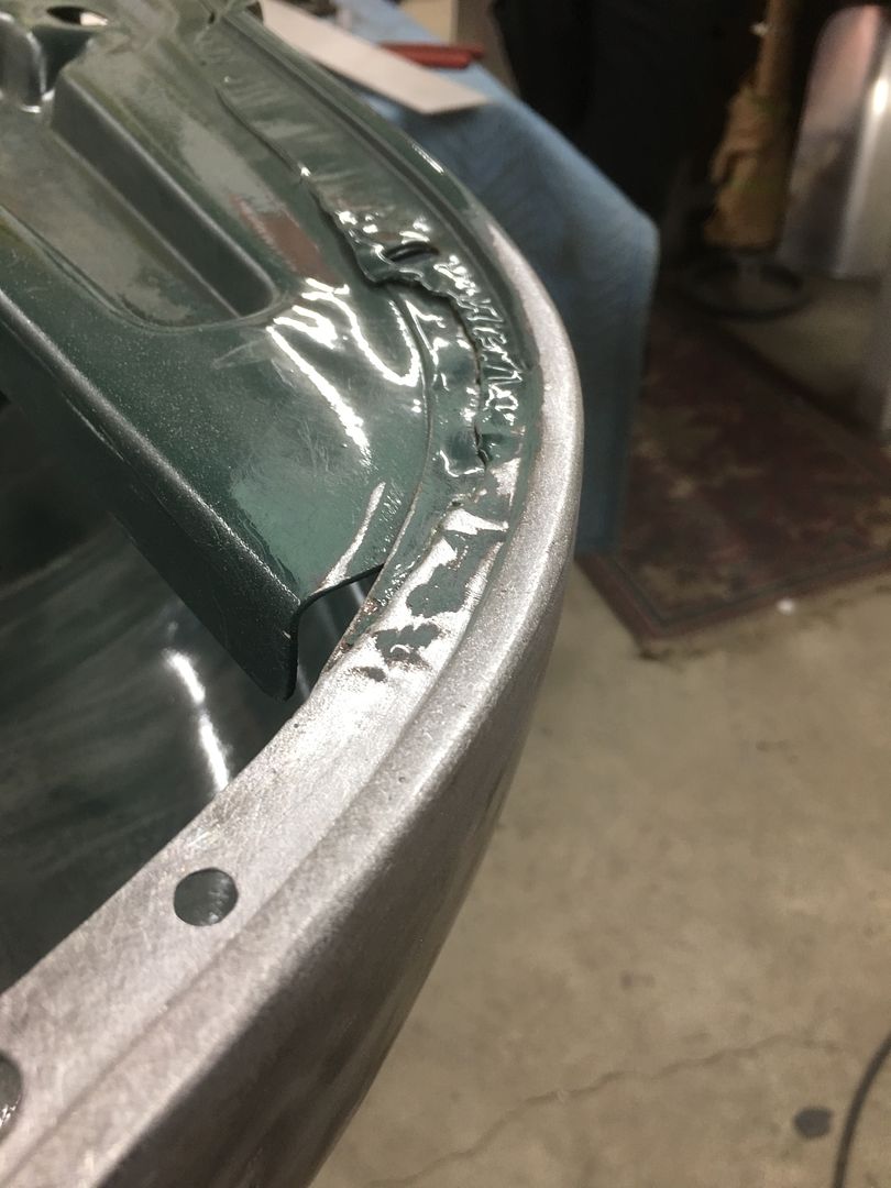
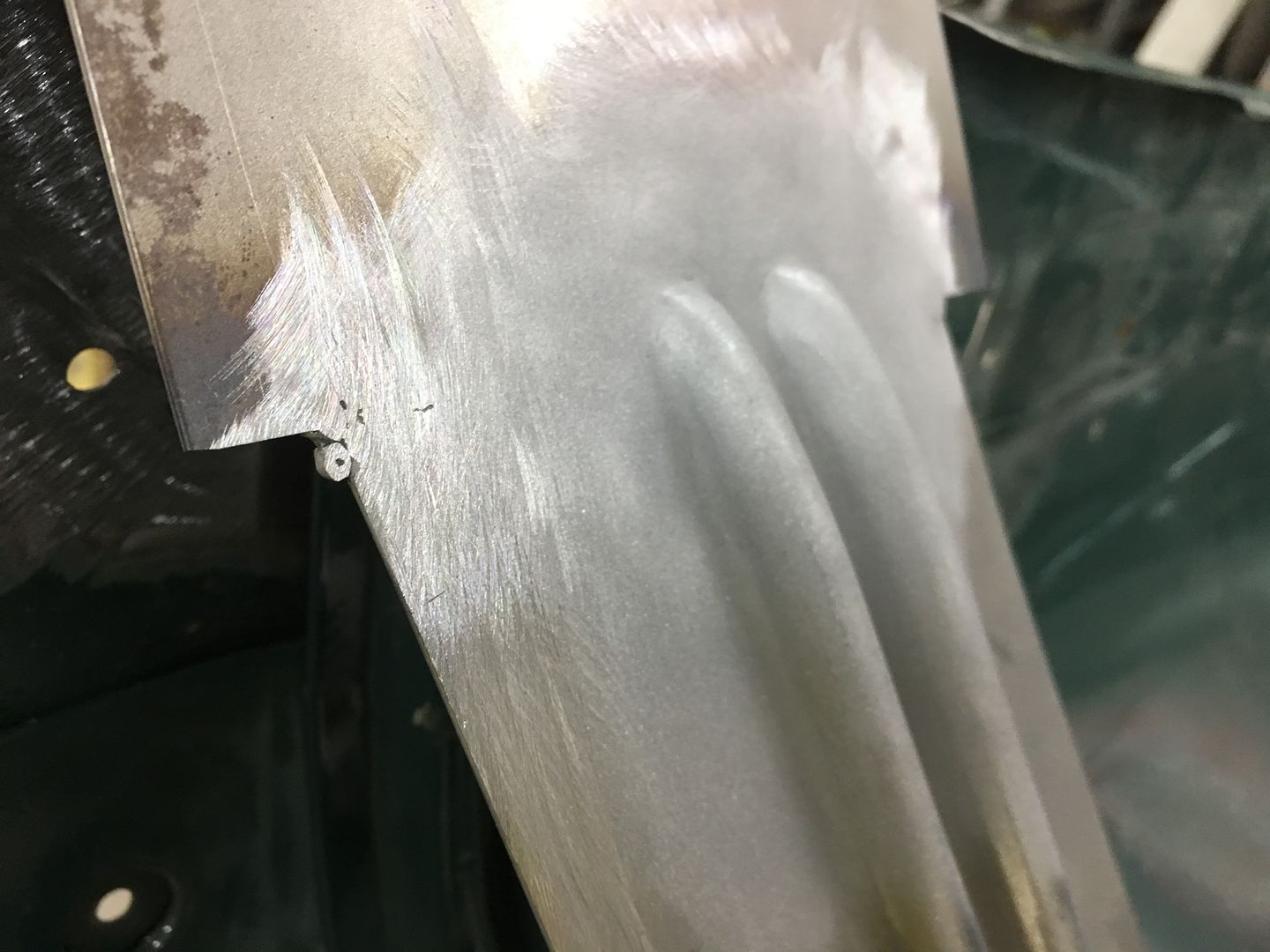
All trimmed and welds dressed, the hood bumper hole is re-drilled in the new patch. Then we notice a bit of filler closer to the nose of the hood (arrow). Let's remove that while we're here to see what carnage lies in wait.
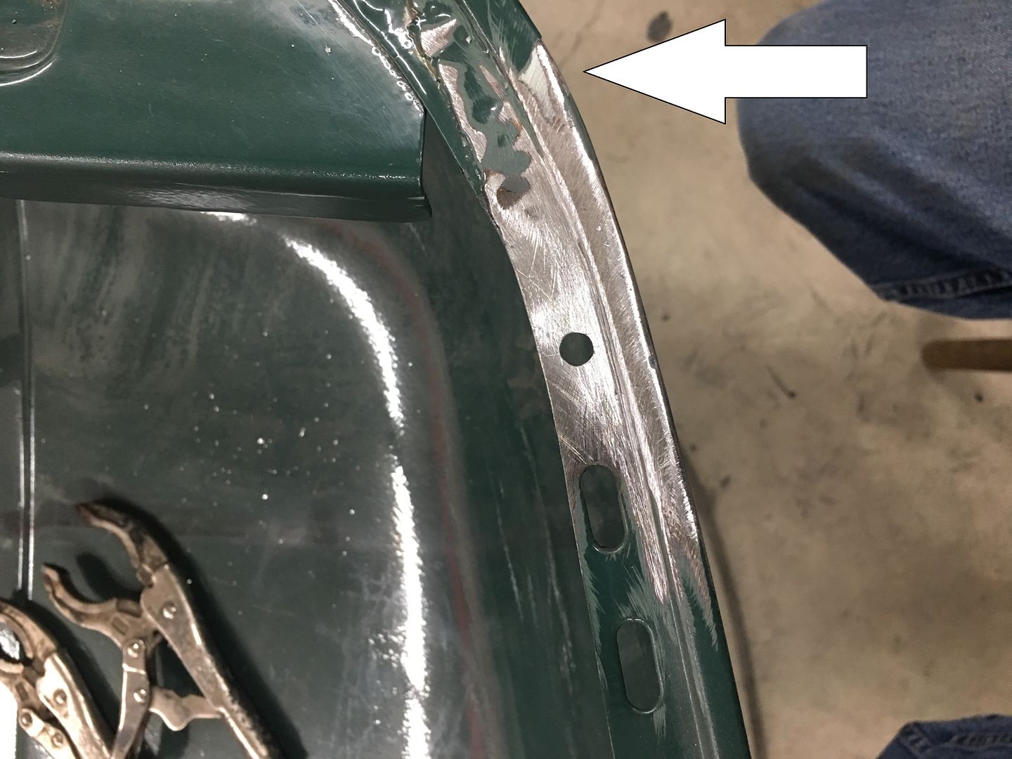
Gotta love this game of dominos..
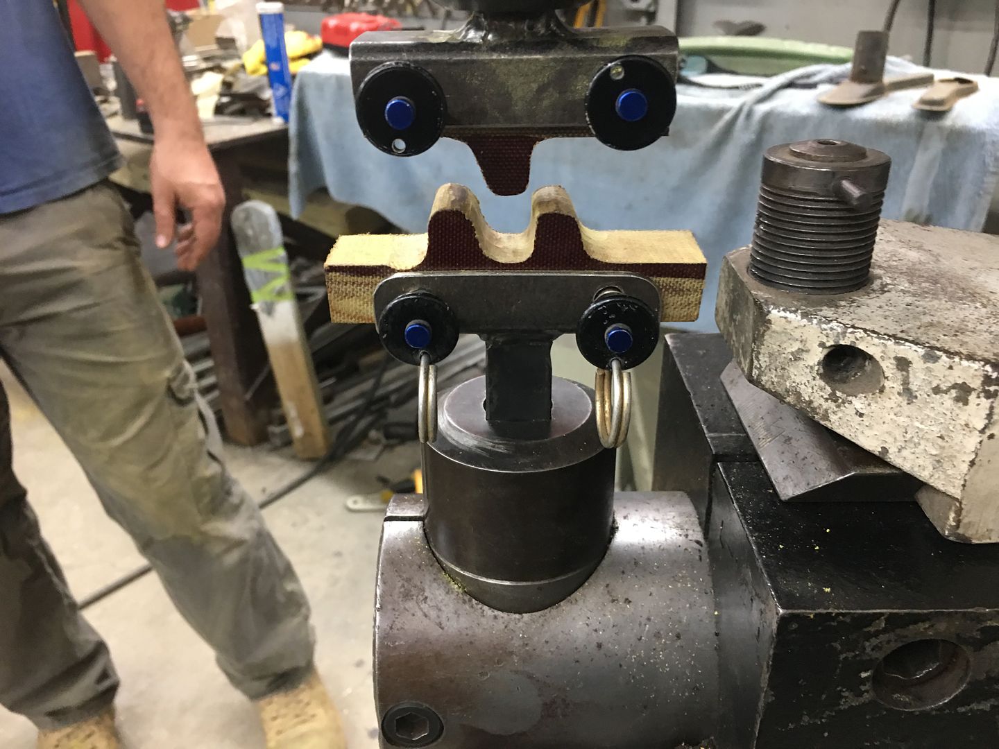
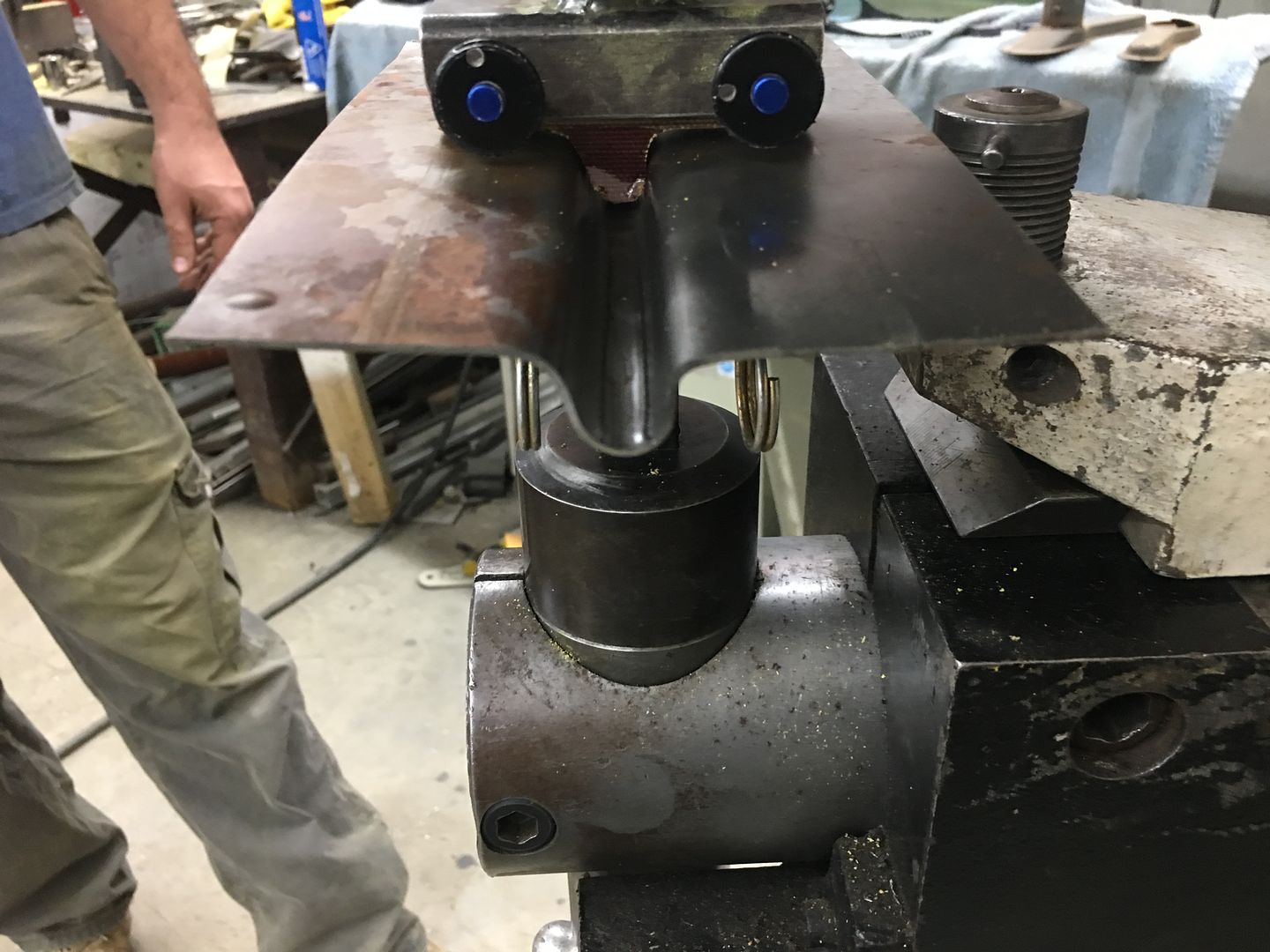
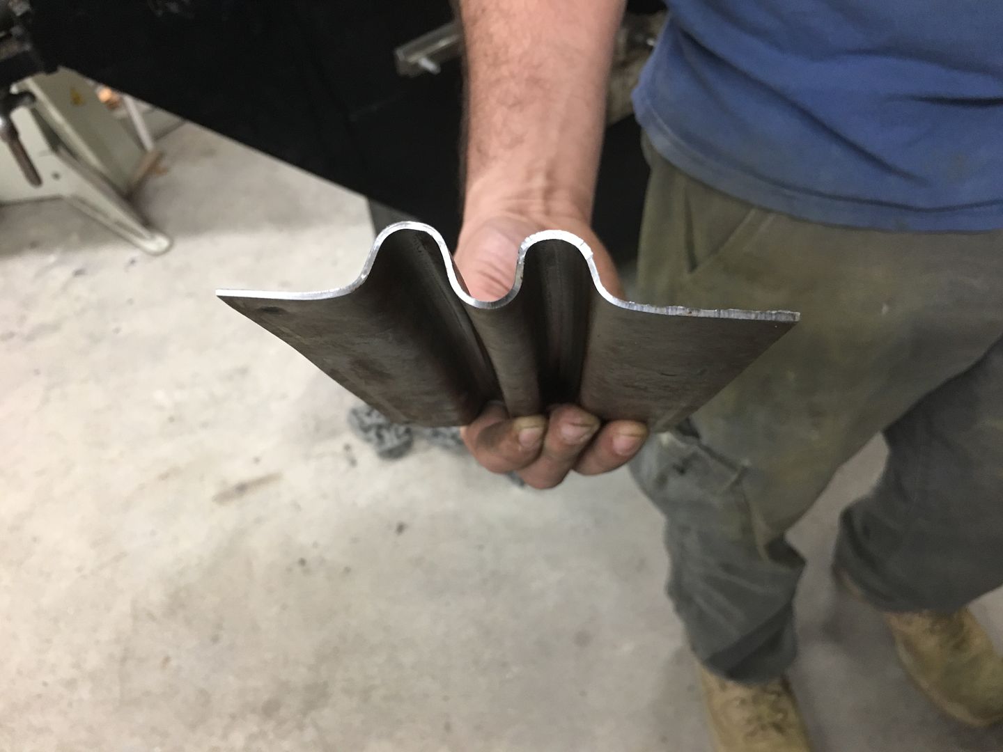
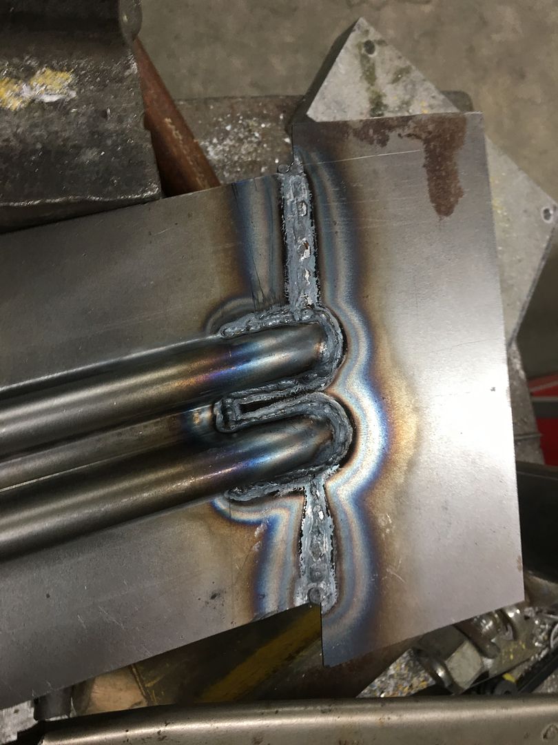
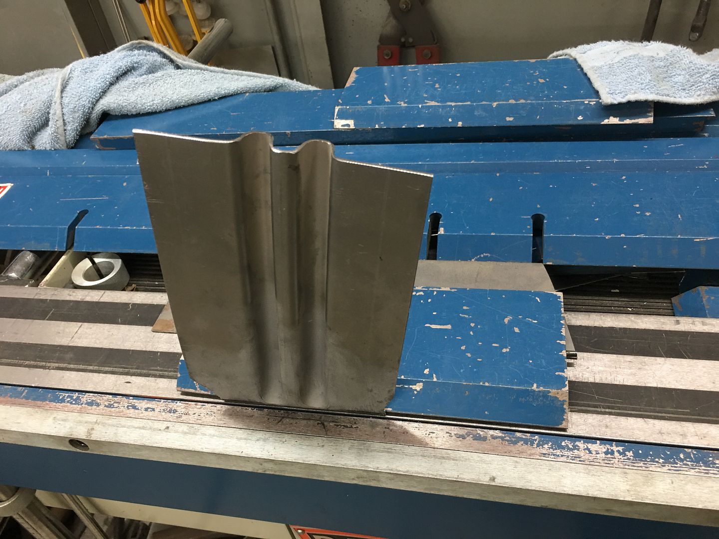
The low area needs to be bumped up, and with little room for swinging hammers, a new tool is in order. Using the South Bend "milling machine" a die is made for the outer portion..
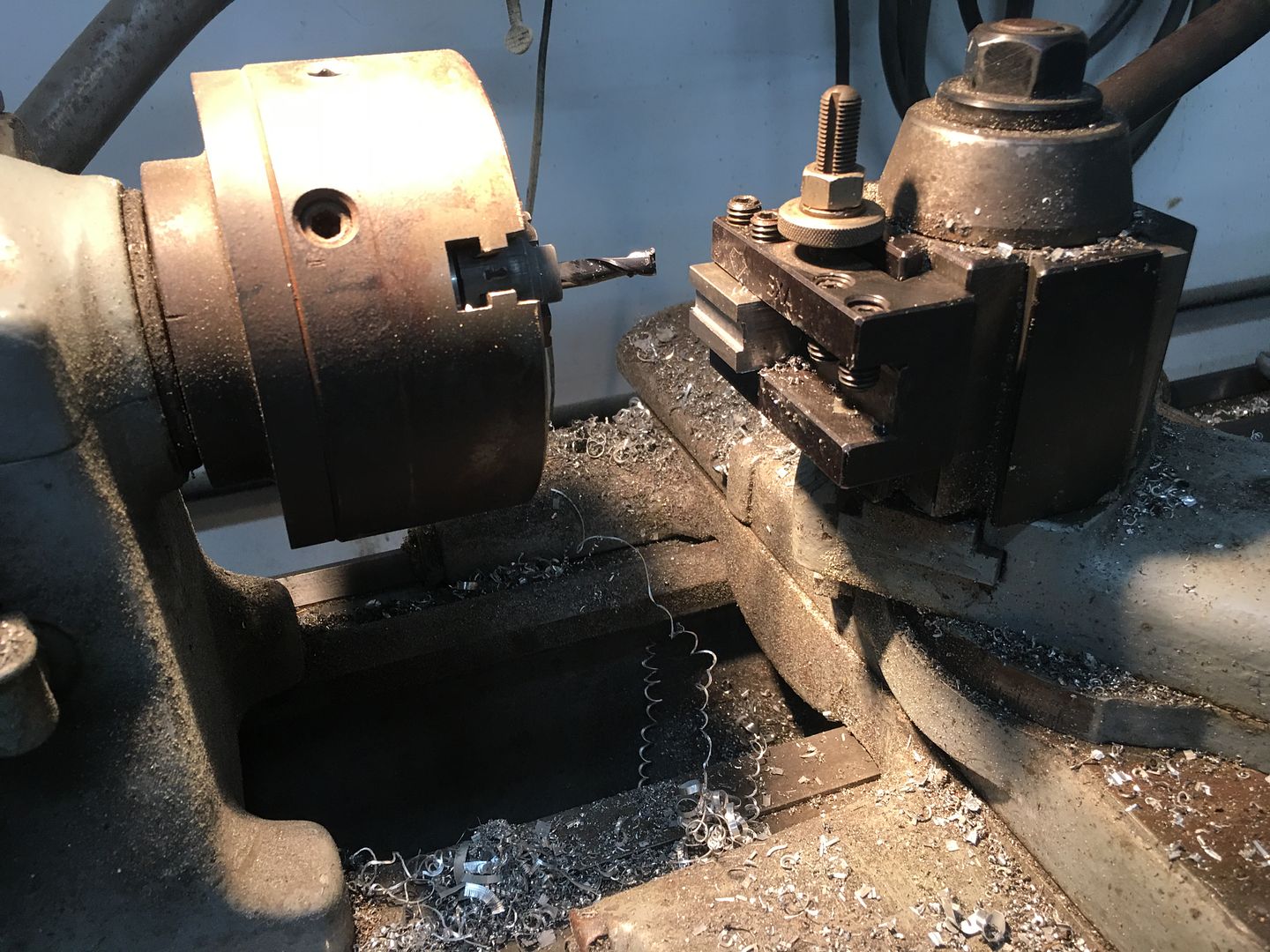
Using a pair of C-clamp vise grips (there goes another pair) the die we made will be welded to one side, the opposite is giving a bit of a trim to better fit in the confines of the slight gap available on the inside..
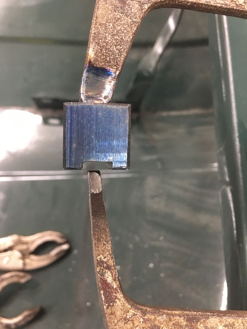
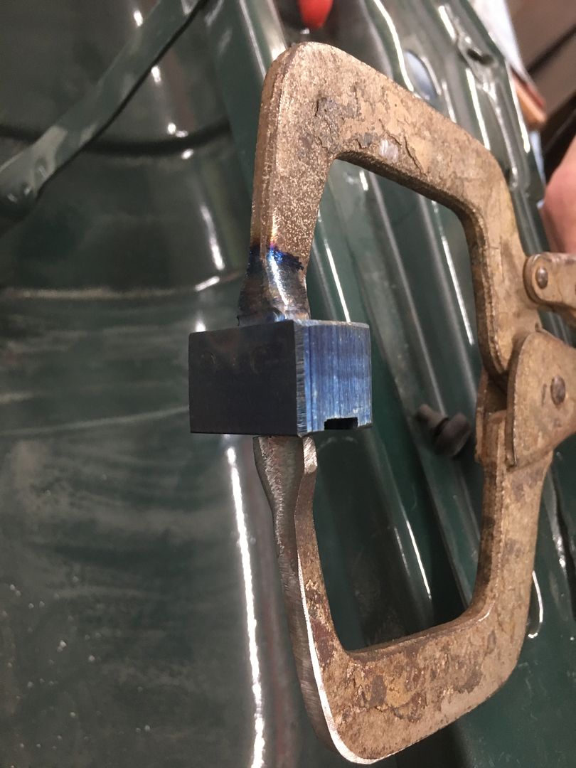
I missed the action shots, but the clamping of the vise grip is used to raise the low areas. Then dressed out for a much better "filler free" lower edge for the hood.
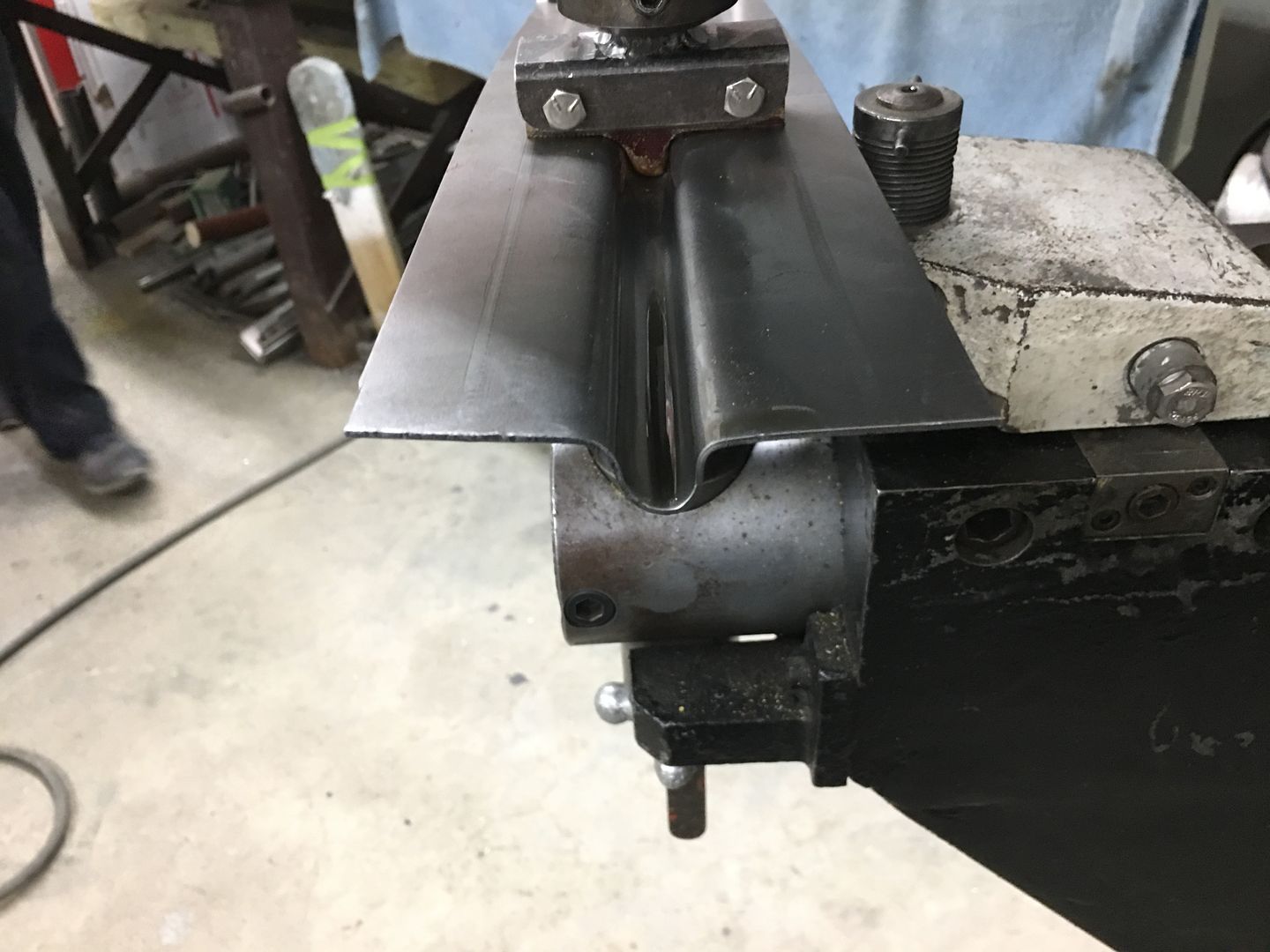
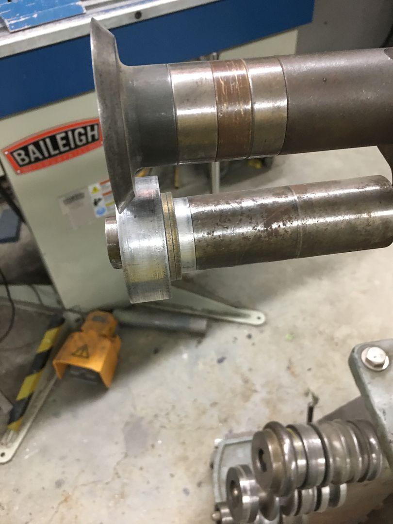
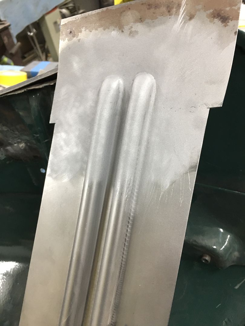
With Mike having completed the dies to duplicate the ribs in the hood brace we did a test run on a piece of 16 Ga cold rolled steel. First upper die addresses middle rib only, way to much drawing going on to expect this out of one set of dies...
Then top die is changed out for the remainder of the ribs...
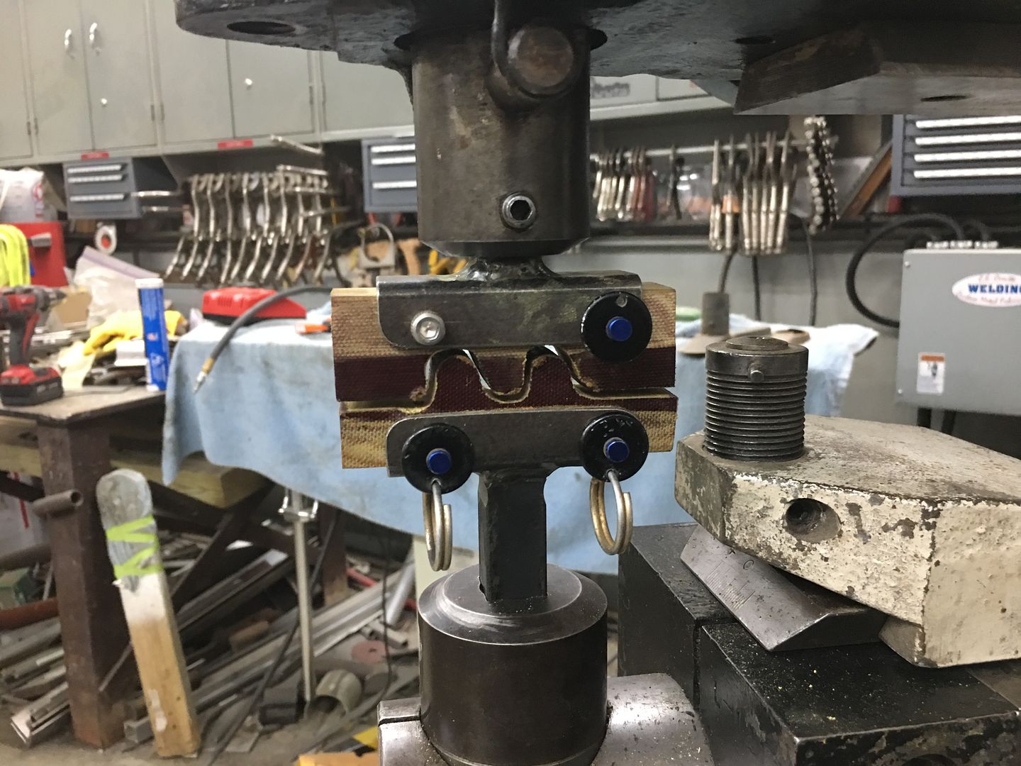
A bit of fine tuning needed, but looks like this process will work to repair the rot in the bottom of the brace ends..
Attached FilesComment
-
-
Very nice. I m following the hagerty you tubechannel build of a 50's GMC. . It isn't a dance rebuild. More of a get it safe and reliable . And use it build , redo. They go deeper into the how to part that most that are not new to the hobby might find boring. But it great they show it . Just like your thread .Comment
-
There was So Much usable info from your last post, I couldn't quote enough to here.
I have a 1952 F5, that is needing a mild redo.
The hood cracks are A Common problem to all of this body style years. Also to the running boards. Junk Yard Parts Safari's only yield parts in the same condition (IF FOUND).
You must have customers with DEEP POCKETS,
to afford the Shop Time Rates alone.
All my builds are, Fix It, good enough to go PLAY with it !!! In so, I'm not afraid to use them for other errands, i.e. Menards, Lowe's, dump runs.
I'm not a Trophy Hunter, I go to shows with them, to "Talk Shop" with other Rusty Iron Junkies.Comment
-
you folks have expanded what I do with my press brake... you willingness to build dies inspires me - keep it up. thxDoing it all wrong since 1966Comment
-
Thanks guys!
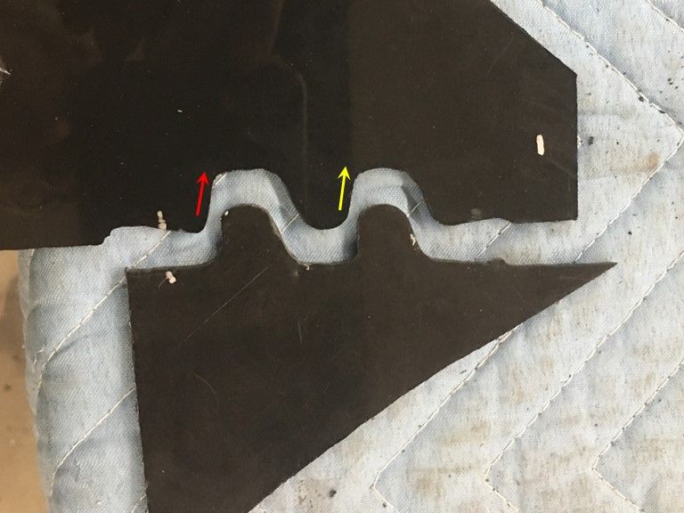
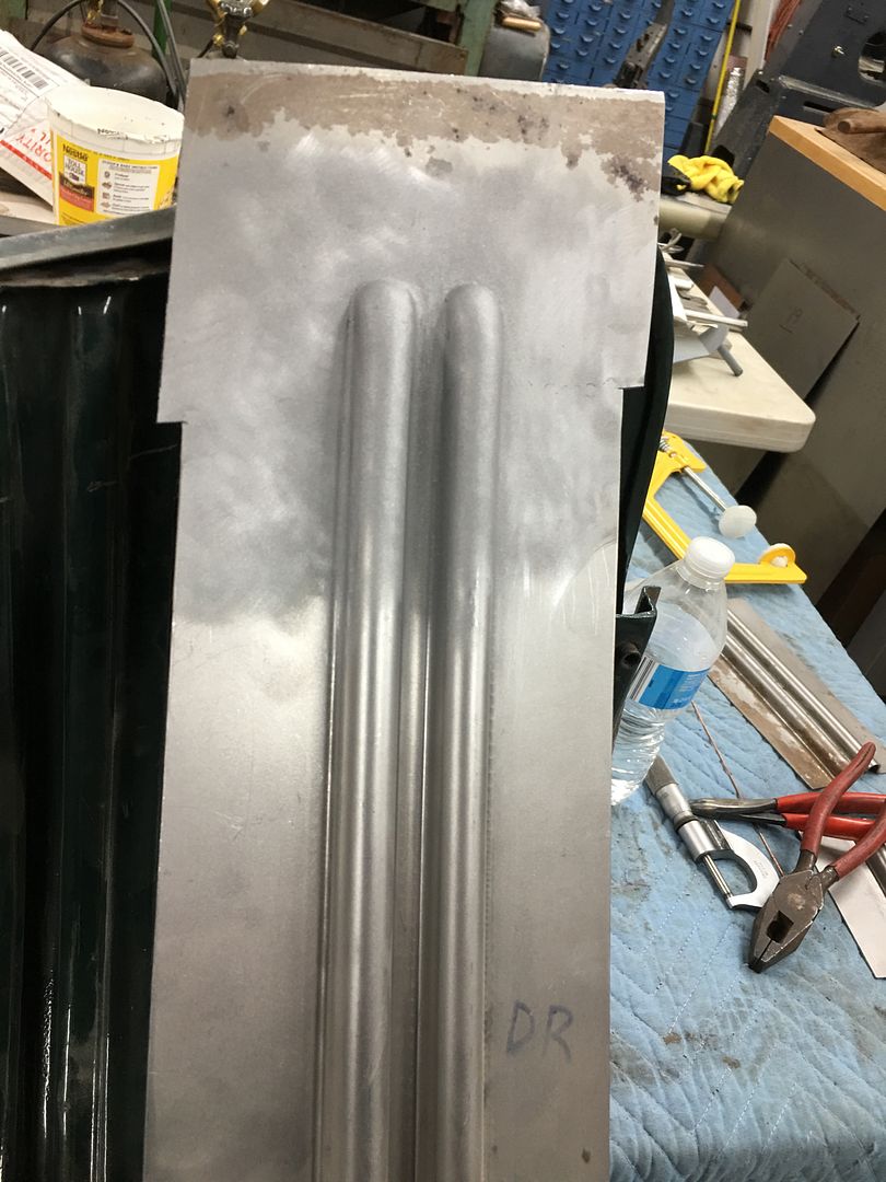
Now to fine tune our dies for the hood brace. Looking at our original profile template, the first upsweep (red arrow) and second upsweep (yellow arrow) are both nearly vertical as compared to the opposite side.
Our first test run shows the first upsweep spread too wide, not enough vertical...
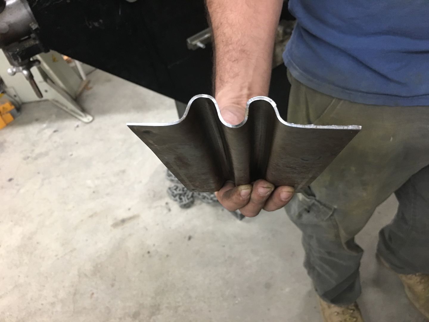
Looking at the die that was made, a bit too much material was removed such that this vertical feature was lost...
So a new die was made for the top, this time out of aluminum. The phenolic is somewhat easy to cut out but does have challenges in making crisp bend details, so lets see if the aluminum helps out..
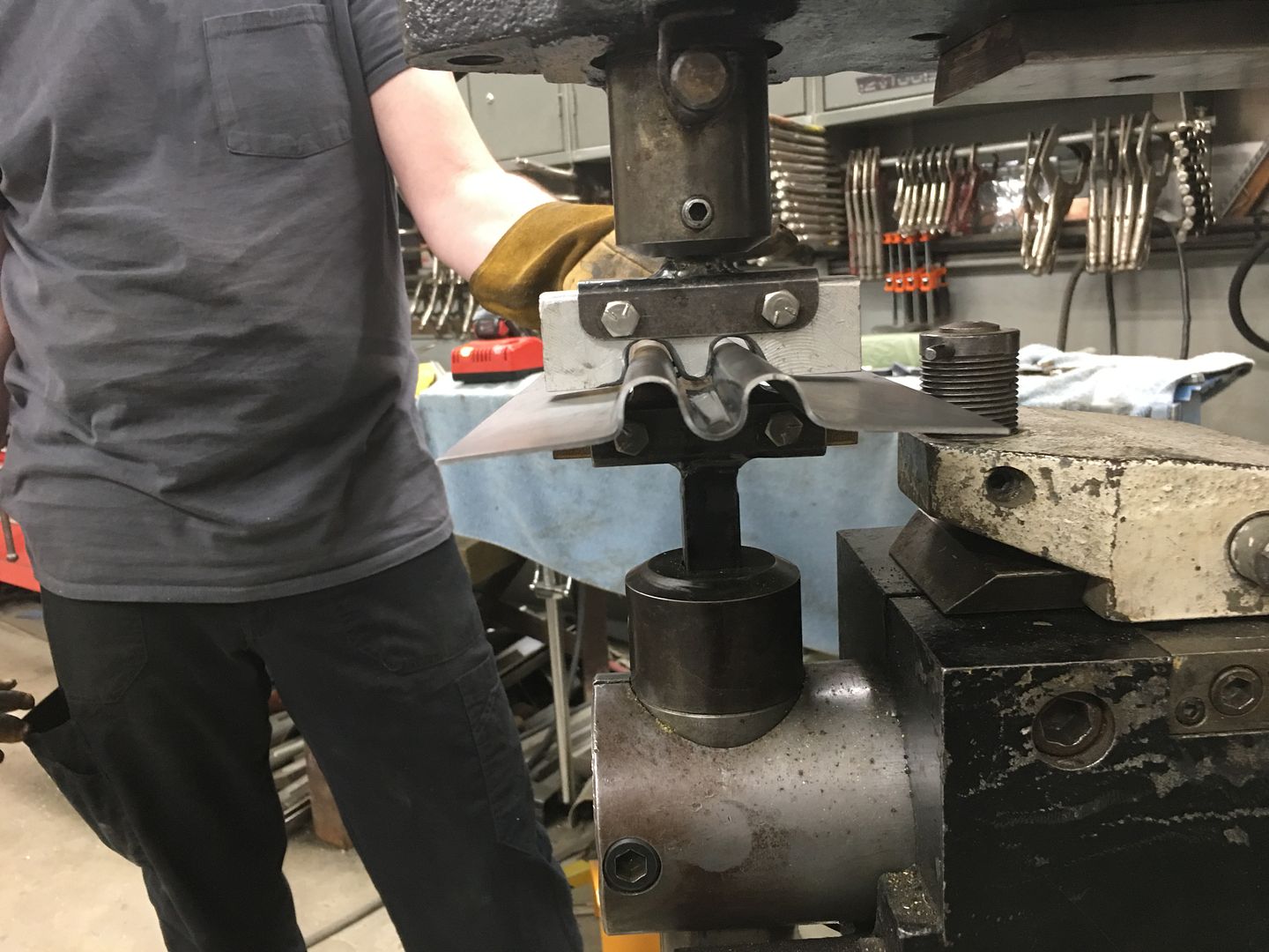
Next run, this time we'll do two panels in case they work... First pass to draw the metal into the center rib...
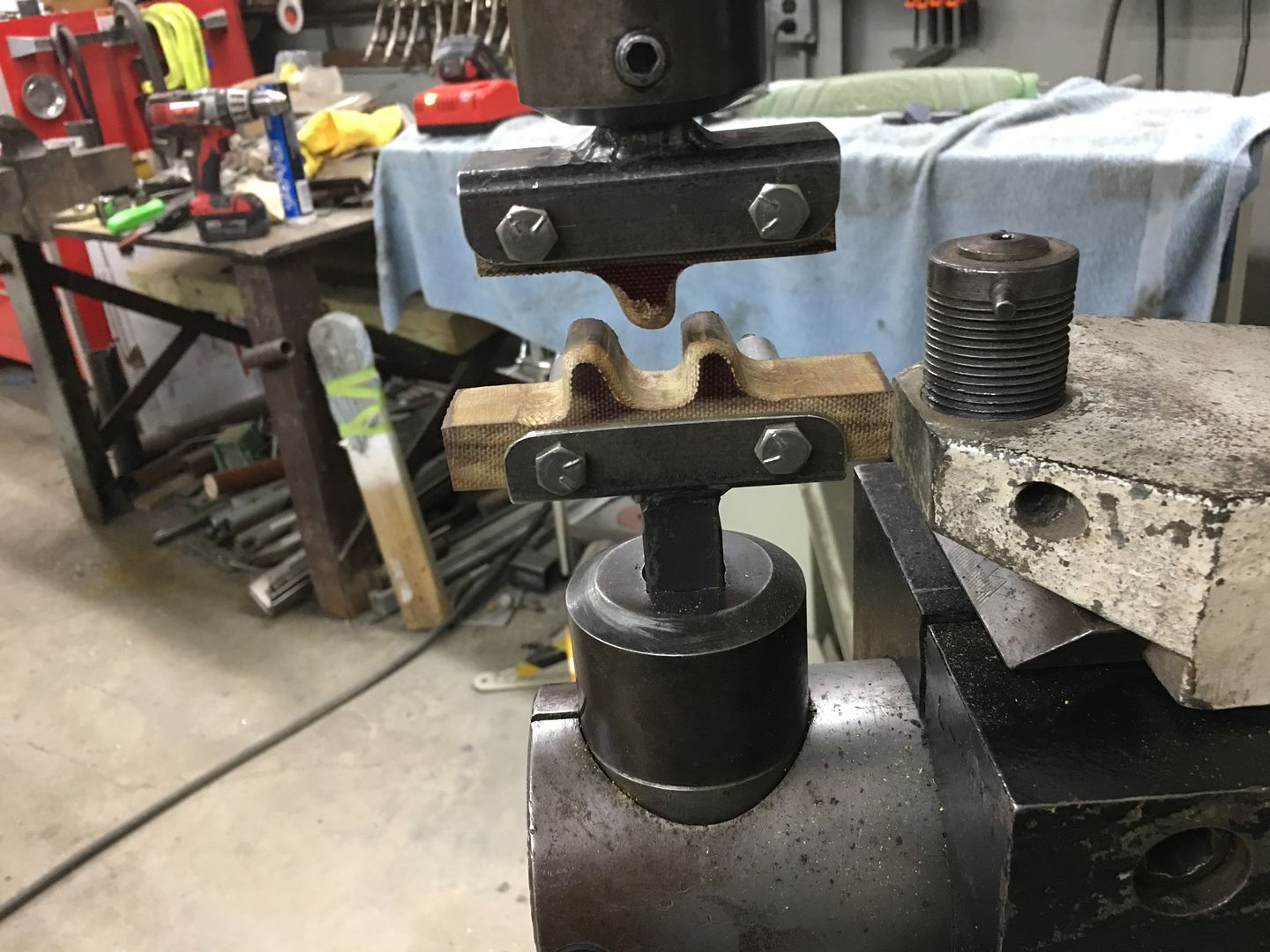
This is about 8 passes, each progressively deeper. The circle fixture to the right in the picture (white base) is used as a back stop to keep our rib centered.
This is about 9/16 of depth, so quite a bit of draw.. Next, the new top die is added and goes through the same 8 progressive passes.. Note in the next picture the vertical upsweeps are both nearly vertical. Success!
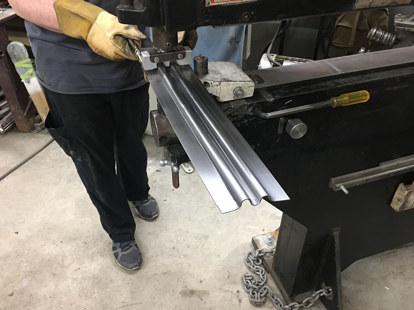
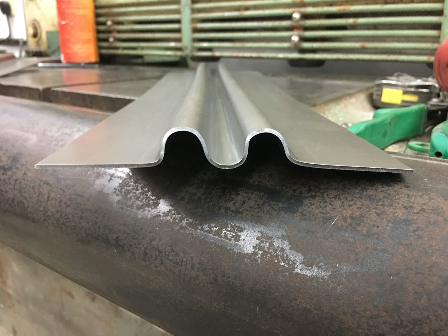
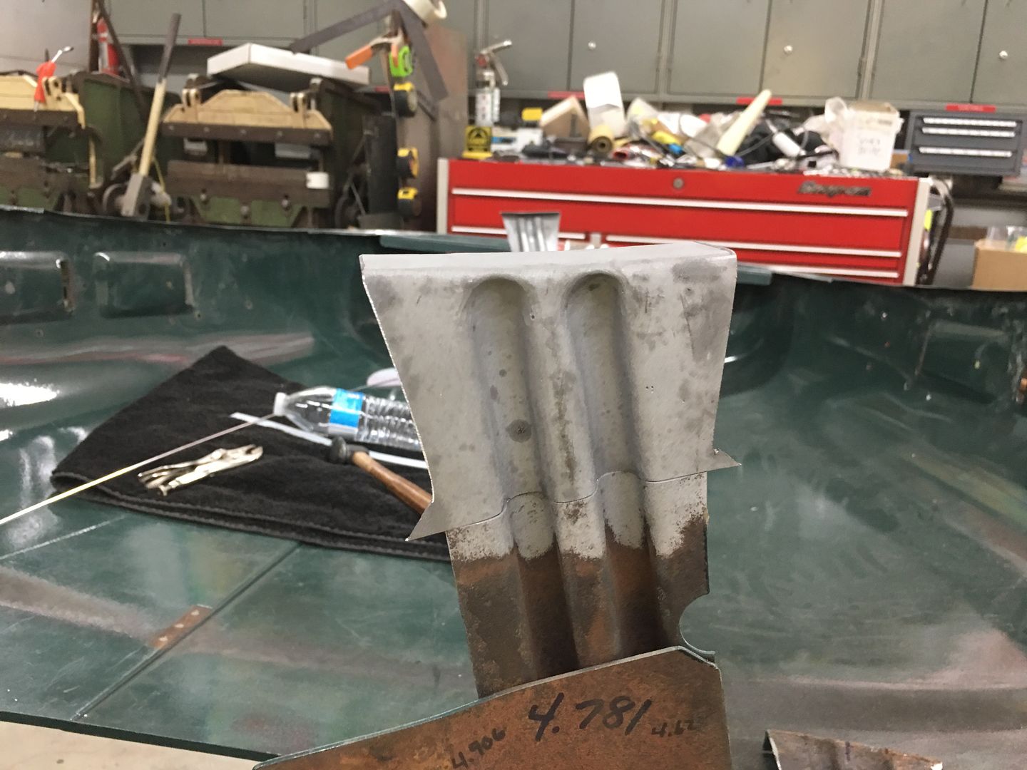
Matching up to the original, this looks like the right replacement.
video version:
.
Comment
-
I ll have to reread this thread when home. As the small phone screen is hell on my eyesComment
-
I'm with you there Eric!
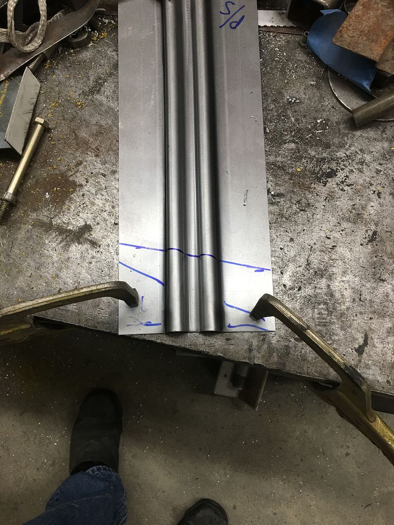
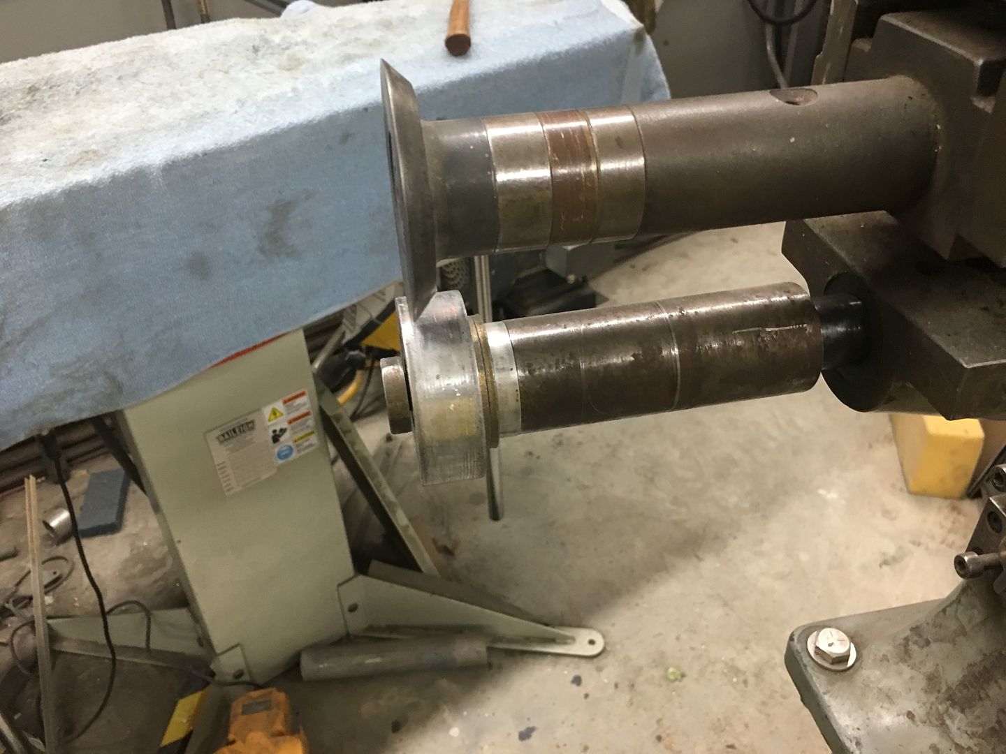
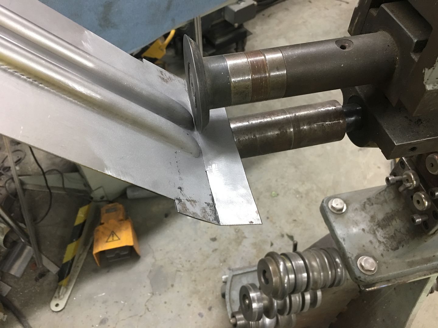
Progress on the hood, the bead details in the brace are offset on the ends to match the hood opening flange. So we use a Vernier protractor to find the angle, and transfer that to our panel. This is where the transition of the taper starts..
Once tapered, the excess is removed from the bottom side and the outer seams TIG welded in place.
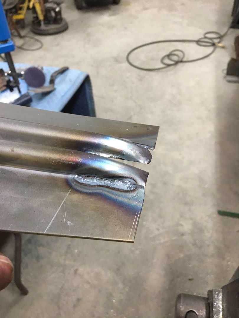
A piece of round stock has a radius added to serve as a hammer form for the beads. They are hammered around and excess removed from the back side..
A piece of 16 gauge cold rolled steel is trimmed to fit and TIG welded in place.
Welds dressed and media blasted..
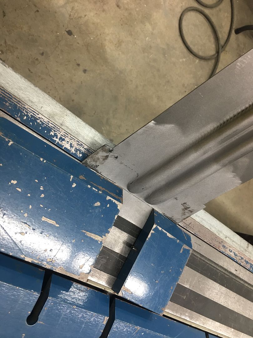
The bend line is transposed from the original. As this bend is slightly convex, it was started using a tipping wheel on the bead roller to a 45* angle, and then finished on the mag brake.
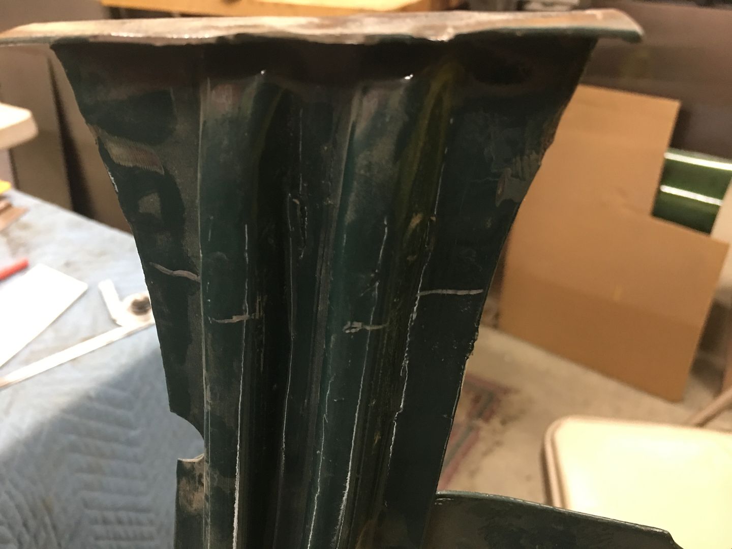
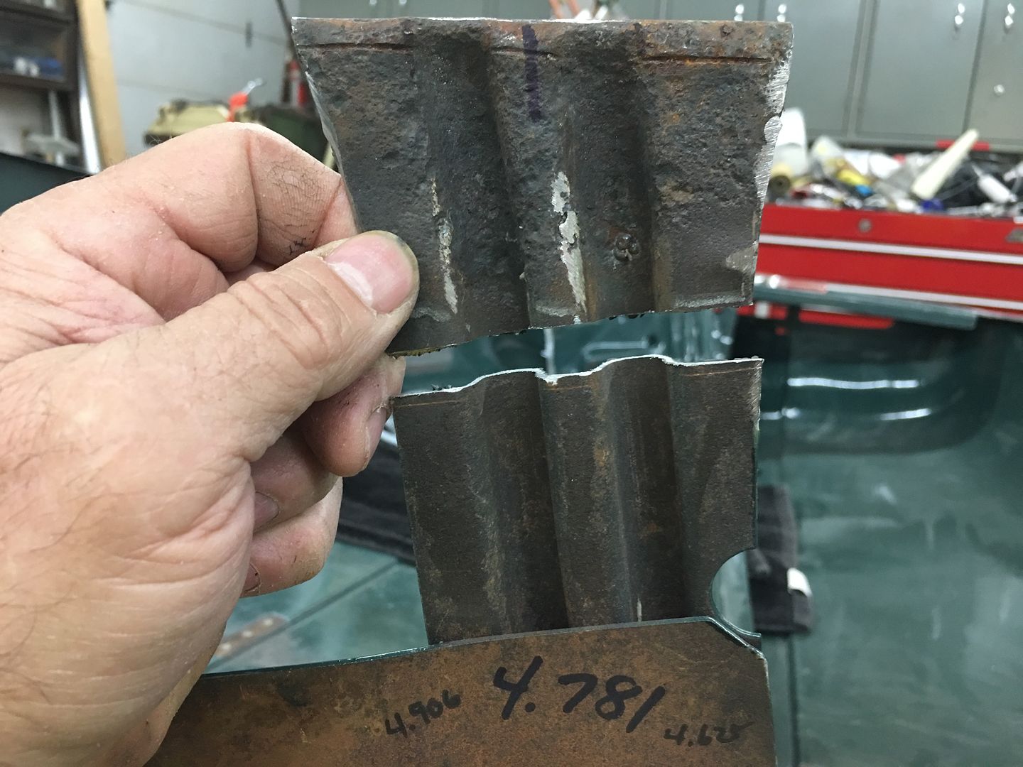
A reminder of the carnage we are repairing:
A profile template is made prior to cutting out the old....
Comment
-
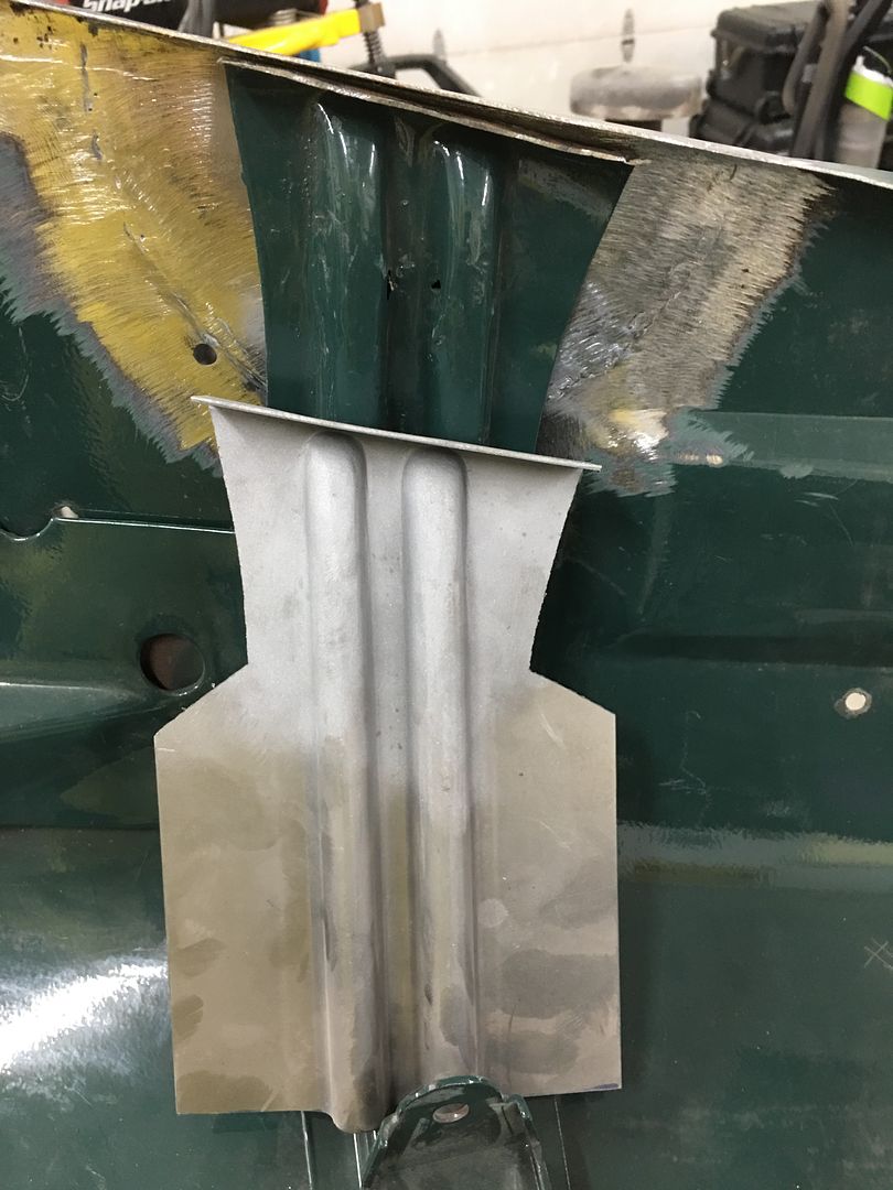
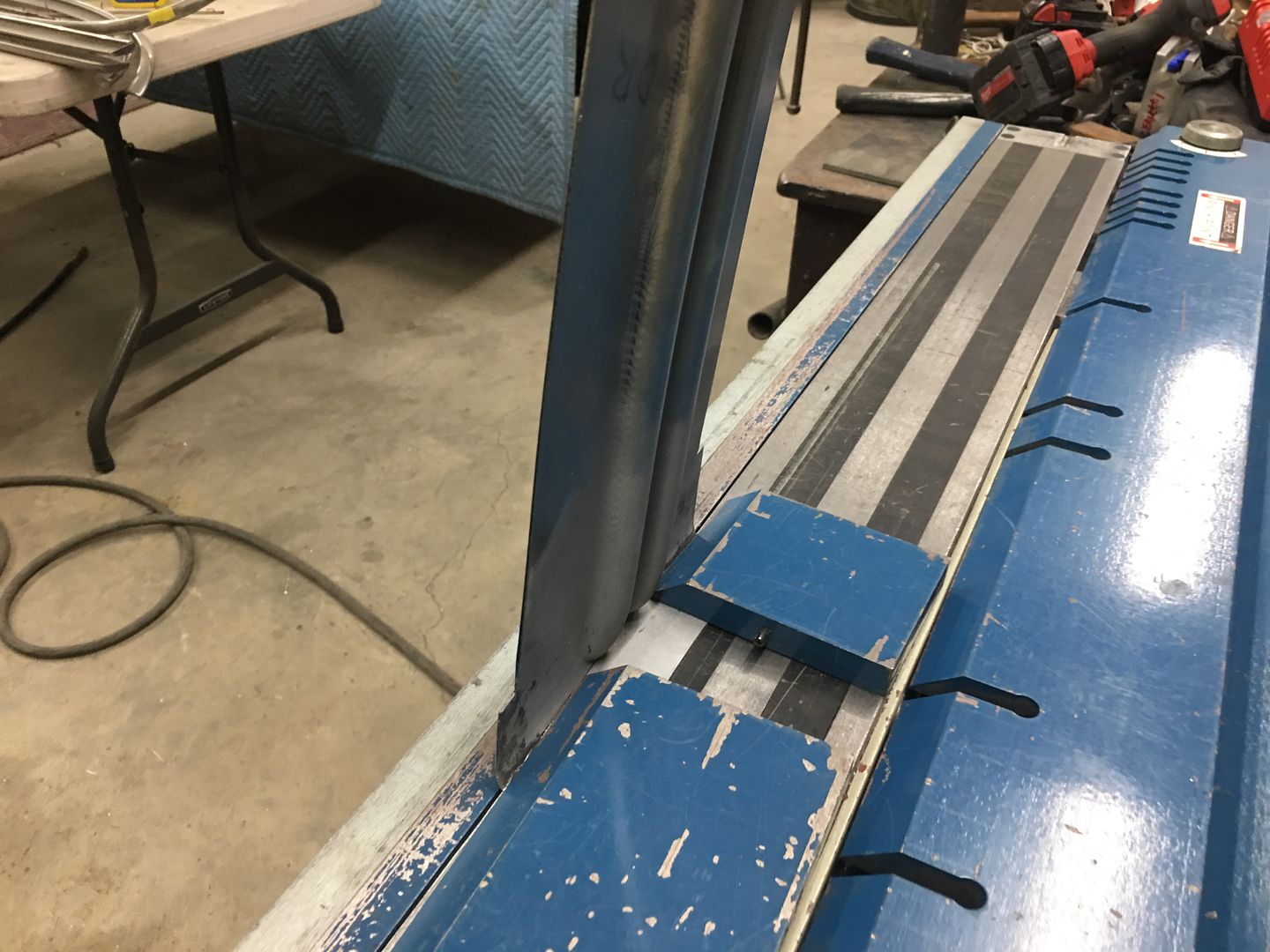
Time to get the hood brace end welded in place. The overall measurement had been taken prior to cutting off the old one, down to the 14 gauge outer plate as a reference. So the new end is trimmed to match this dimension, then held in place with rare earth magnets. The center (inside) rib is aligned and tacked using the TIG....
Working outward, the panel surfaces are aligned and tacked as we go. Note the "batwings" left on the outside of the new brace end (yellow arrows). This will act as a heat sink when we make the outer tacks. Had these been trimmed to match prior to welding, the edge will have a tendency to burn back from the heat.
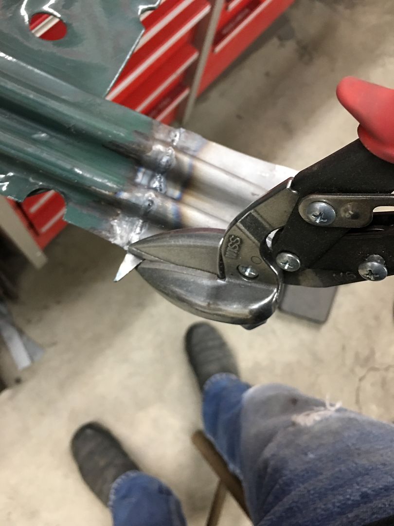
The entire seam is TIG welded and then our batwings are trimmed using offset snips, then welds dressed..
One down......
Comment
-
Starting on the other end of the hood brace, this one not as rotted as the other but has issues just the same. One of those "while we're here" things....
The ribs are trimmed and ends rounded.. A piece of flat 16 gauge is trimmed to fit..
tacked together....
….then the photographer went on strike until we got to this...
We'll get this trimmed and installed tomorrow..
Comment
-
incredible work as usual. makes my "fab skills" look like the work
was done by stevie wonder while having an epileptic fit........Comment
-
Thanks for the comments.. And we all start somewhere, I'd be embarrassed to show what I was doing 25 years ago.
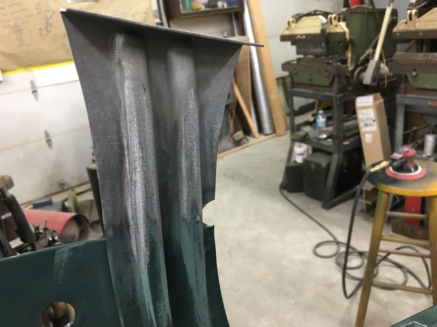
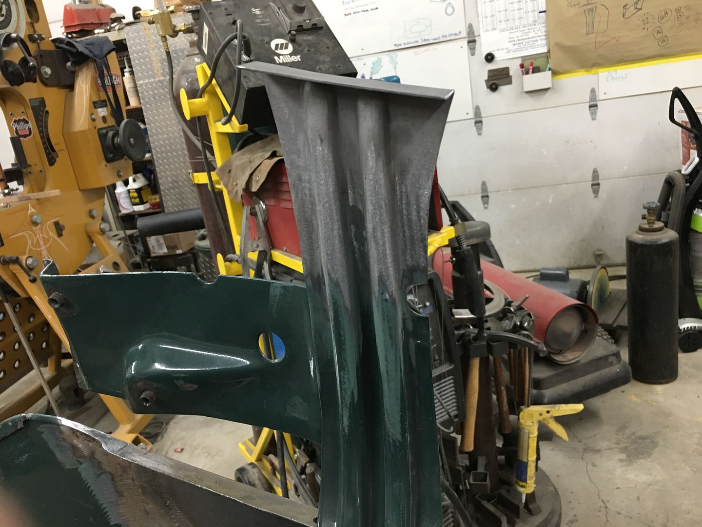
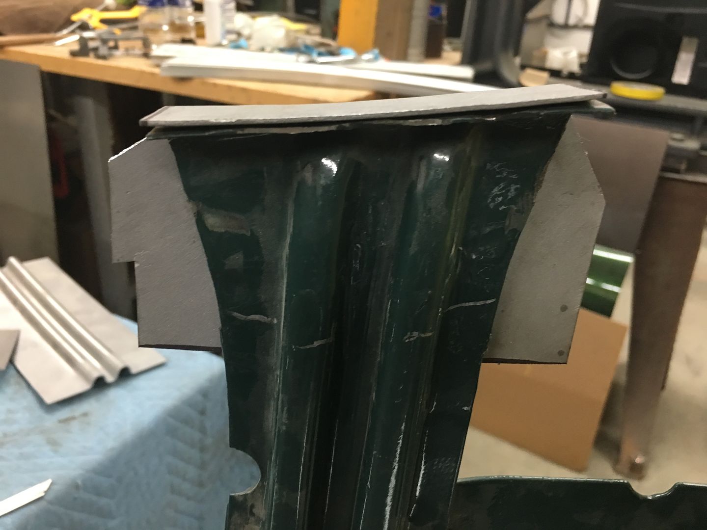
More progress on the hood, here is the other end of the hood brace.
Looking at the back side, you can see where a few holes were welded closed the last time it was painted, and the severe pitting and new holes that we have. A testament to the fact that what shows is always the tip of the iceberg. Although better than the passenger side, this is definitely one of those "while we are here" things. Do it right, do it once. (grinder marks were mine)
With our new replacement all one piece, the next step is to bend the flange that spot welds to the hood skin. A tipping wheel in the Fasti-werks bead roller makes quick work of it. The bend line was transposed from the original and an initial pass under the tipping die marks the crease line a bit better, Then successive passes are made, lifting slightly with each pass. This is done until the beads interfere with the tipping die.
Then the partial bent flange is clamped in the magnetic brake for the remainder of the fold. This brake allows us to use a die on either side of the bead details, where a full die may inadvertently push in on the beads.
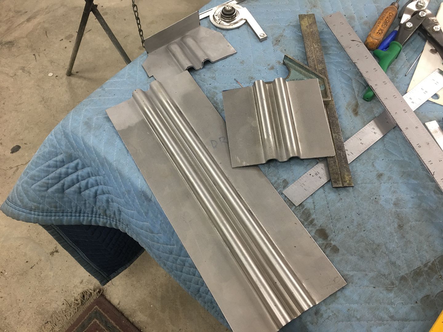
End gets cut to length and marked for initial trimming
Looks like we may have enough bead stock left for another couple of ends.
That's where we left off yesterday, we'll see about welding the new end on today..
.
Comment
-
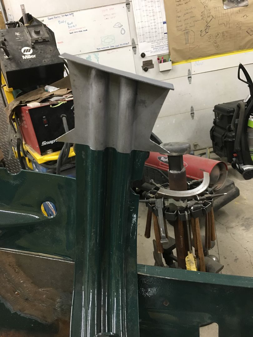
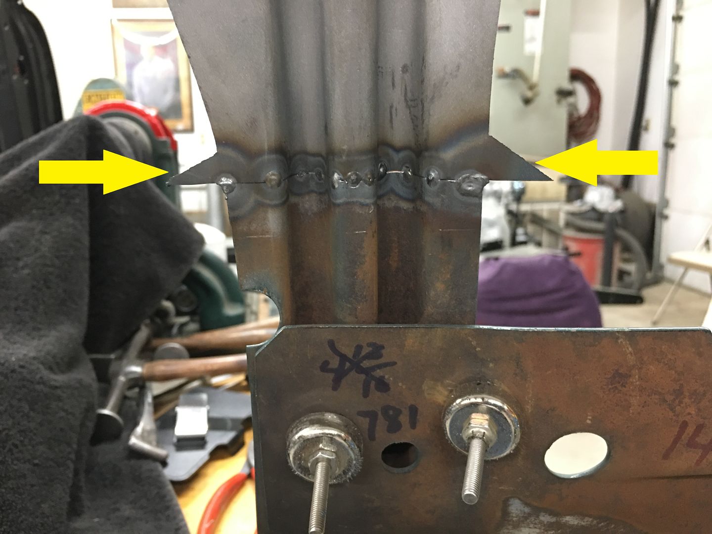
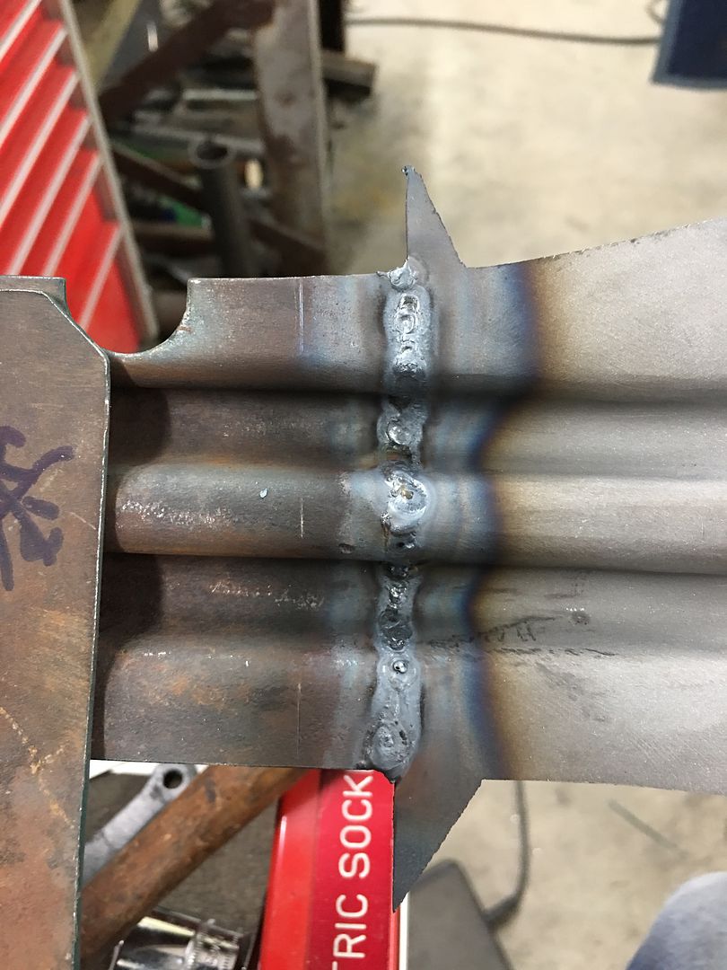
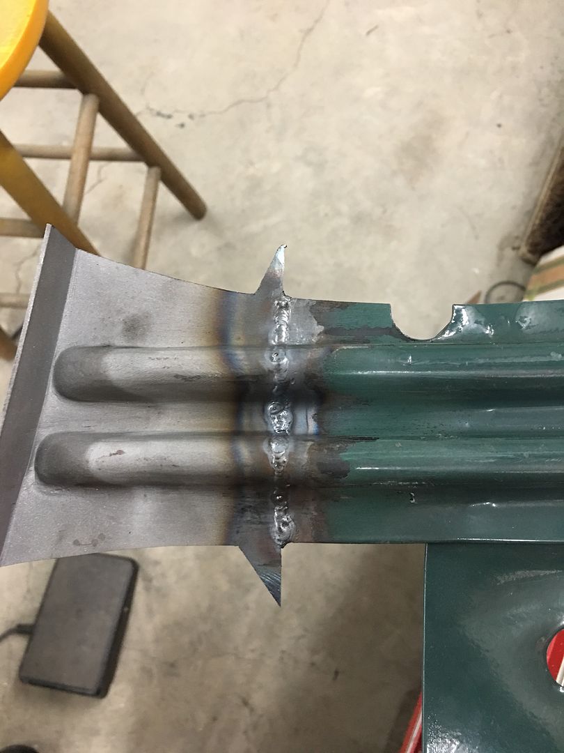
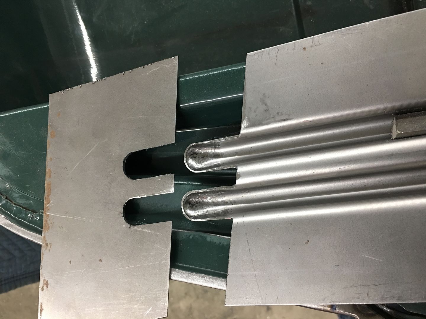
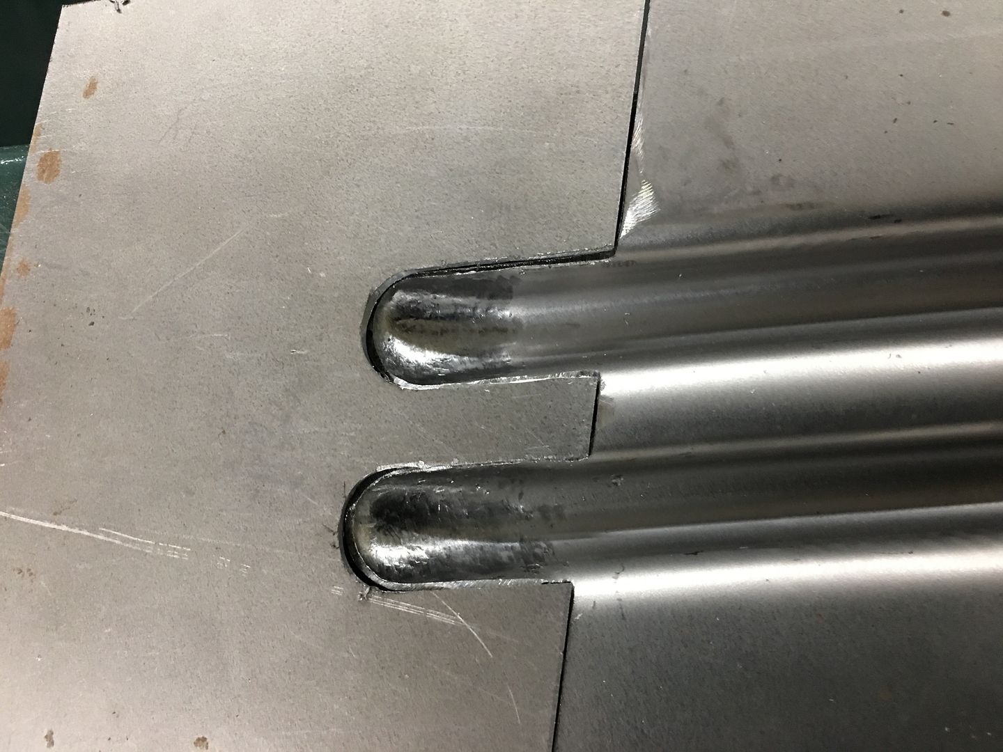
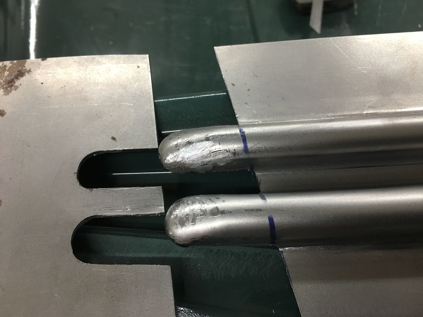
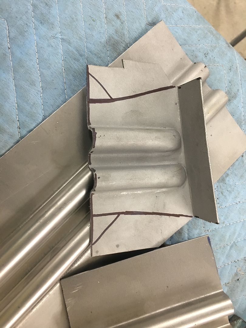
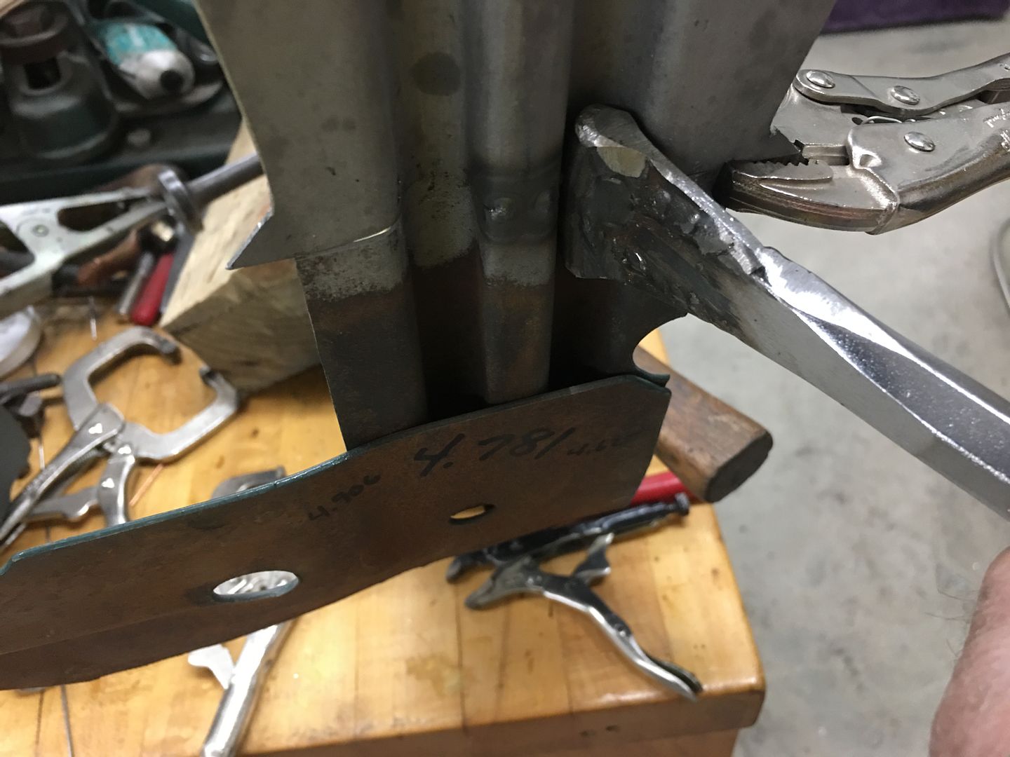
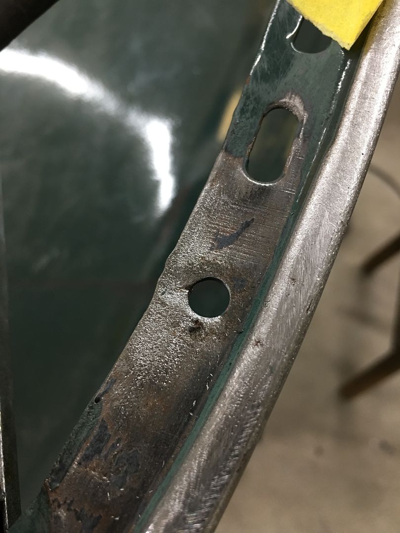
Our last end for the hood brace. Off with the old.....
Then it gets trimmed to our scribe line and the end media blasted in prep for welding. Our new end is test fit and trimmed until we get the right distance to our reference marks. The "batwings" give us a heat sink at the edge for less chance of burning back the edge at the weld.
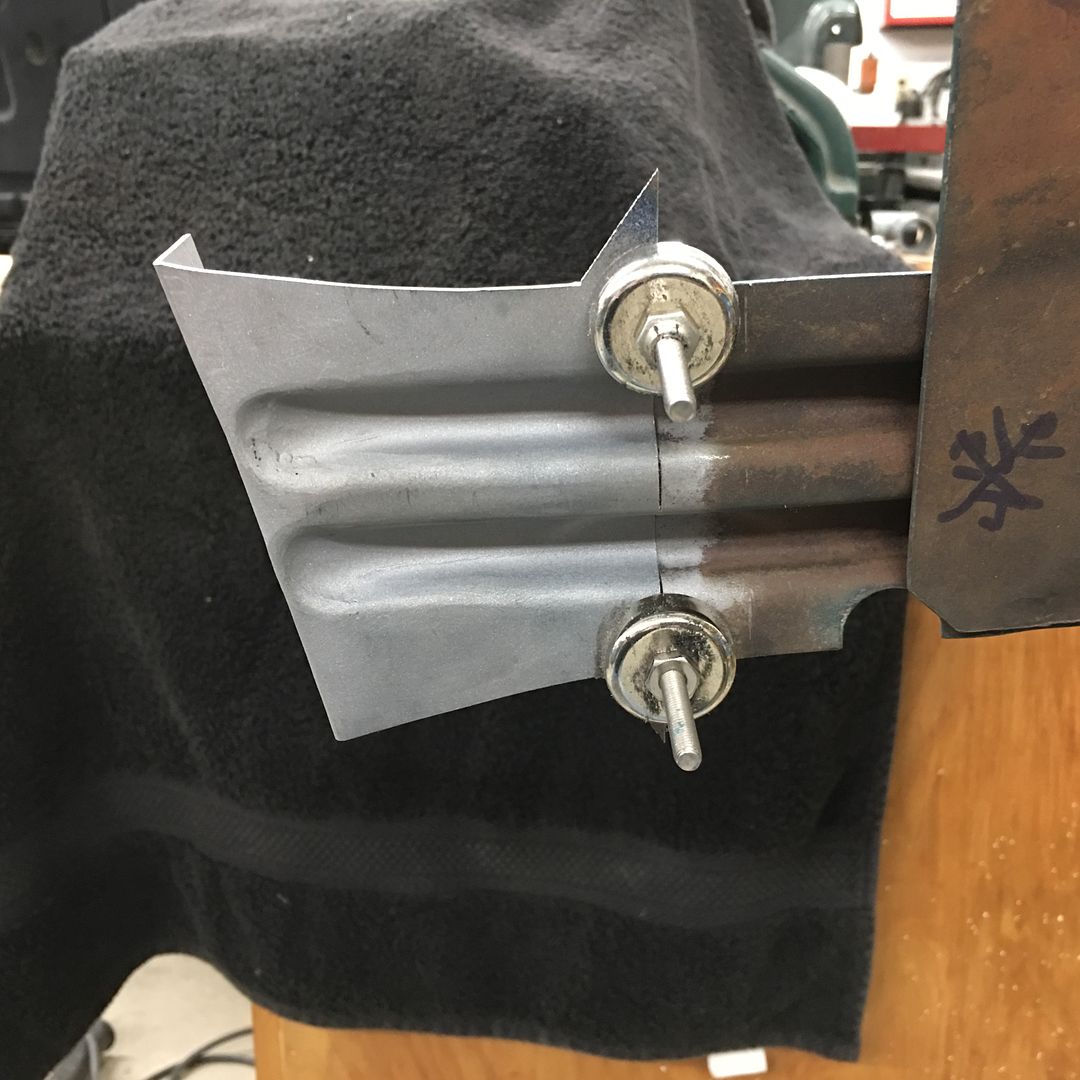
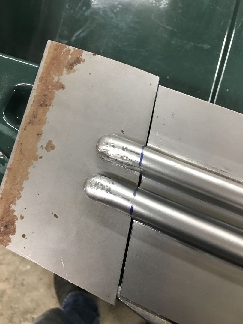
The center rib is aligned both on the sides and the face, and tacked in position using the TIG.
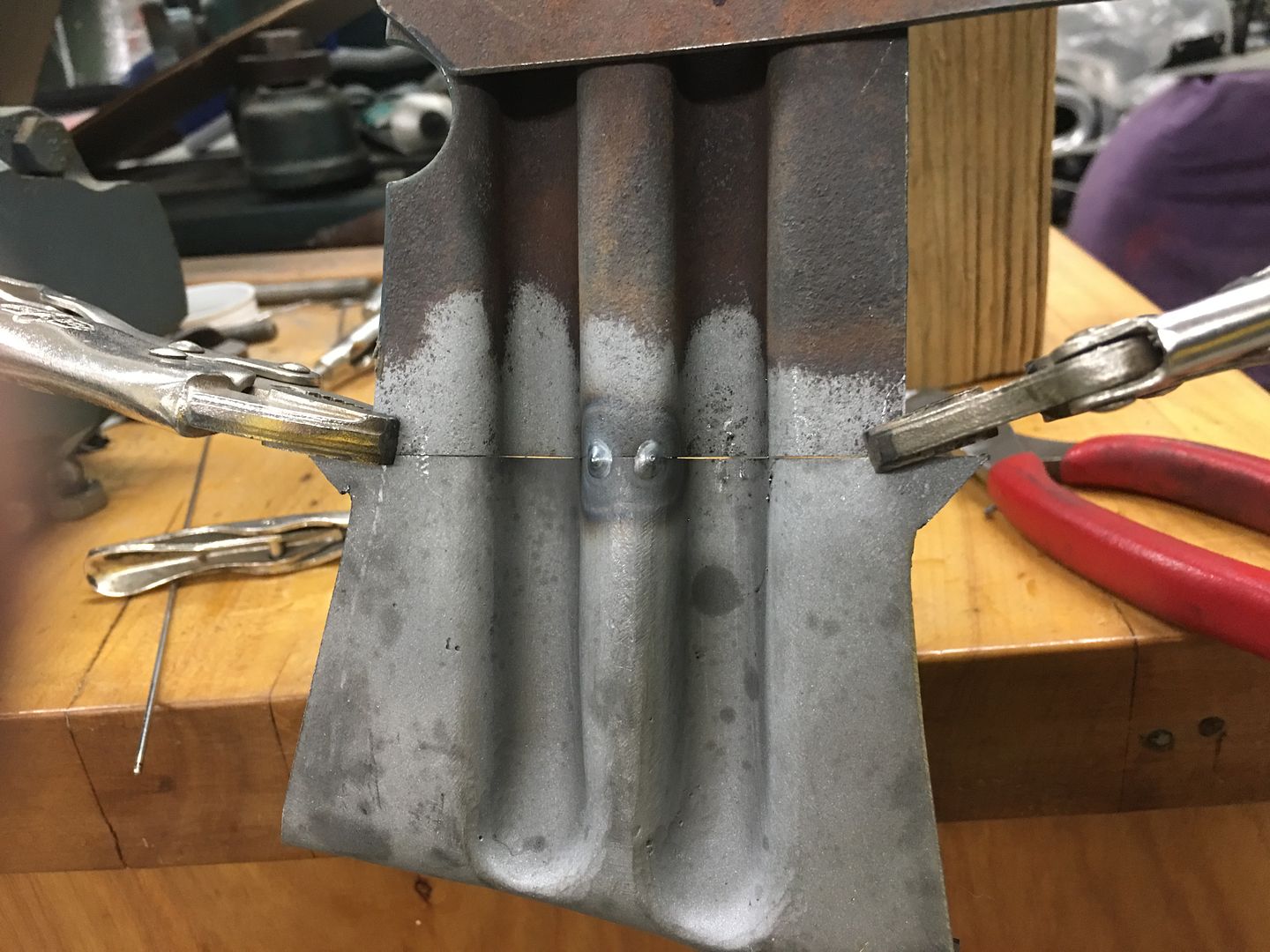
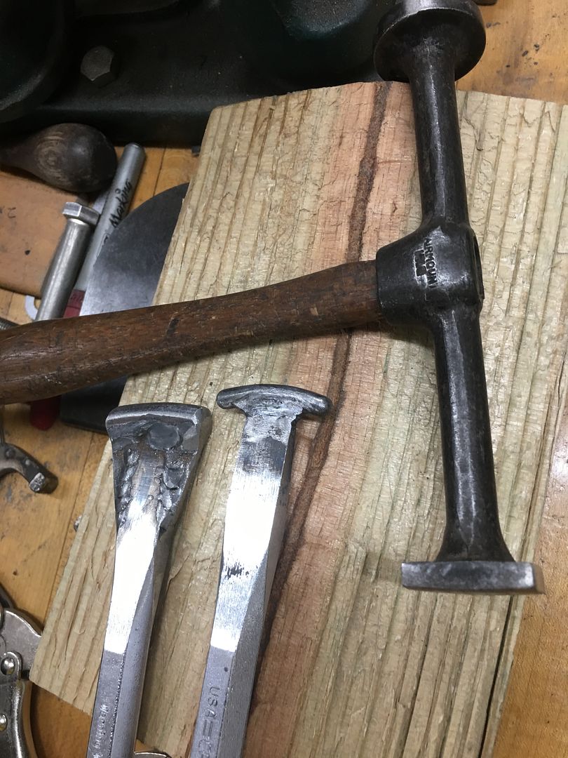
The pieces are aligned as we work outward, tacking as we go. A "corking tool" is used as a dolly where any bumping may be needed for alignment.
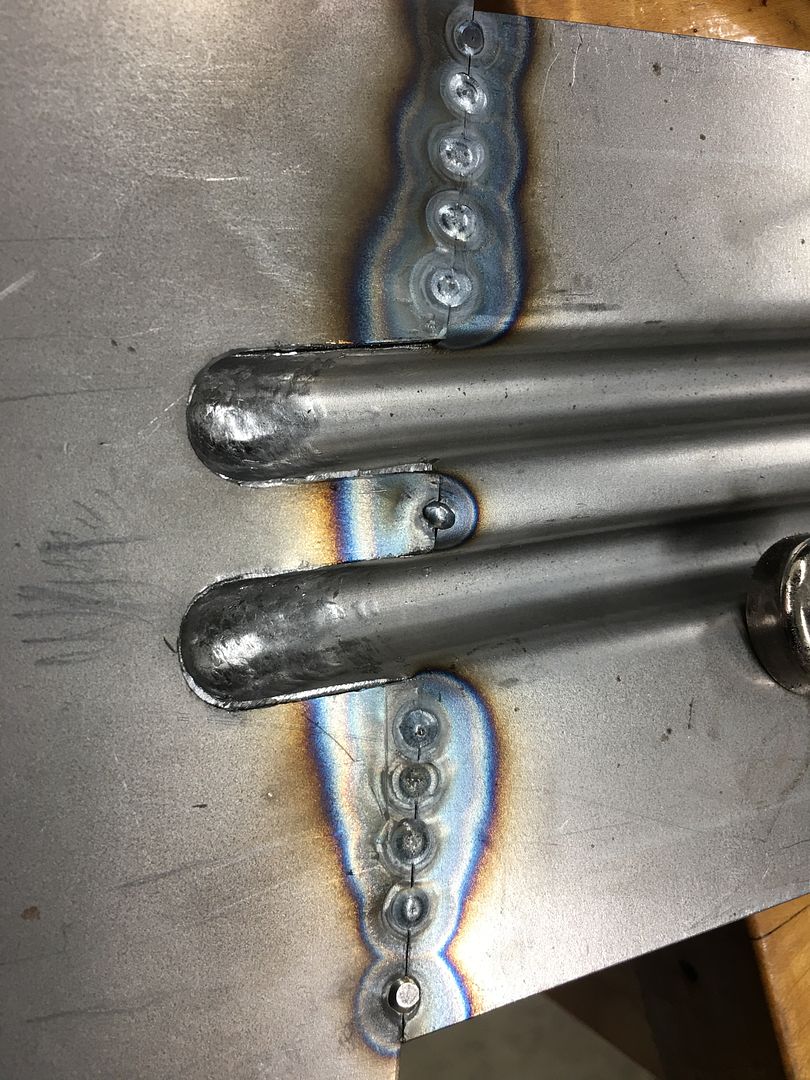
Tacked...
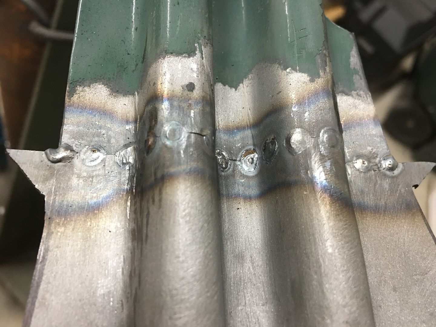
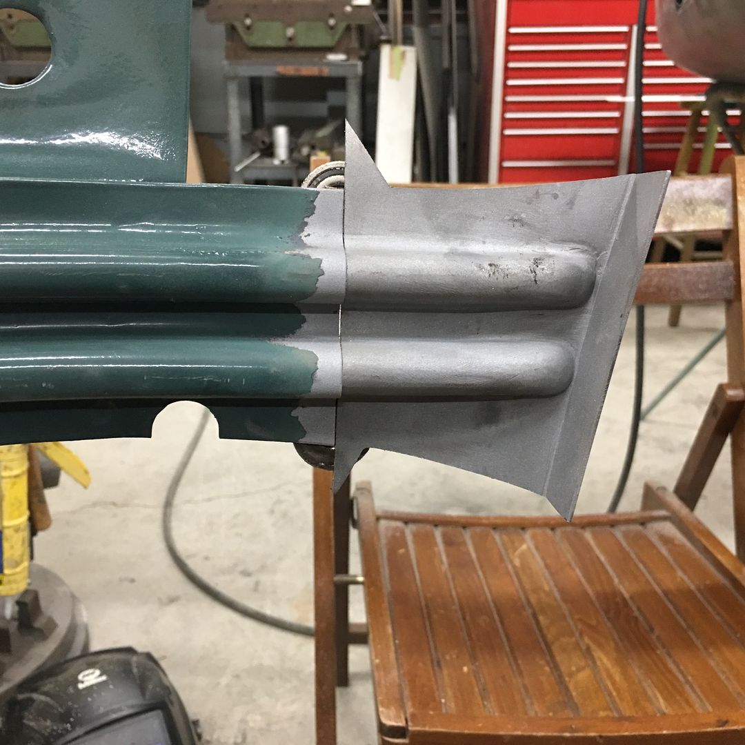
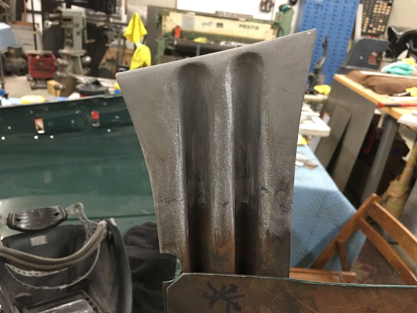
Welded....
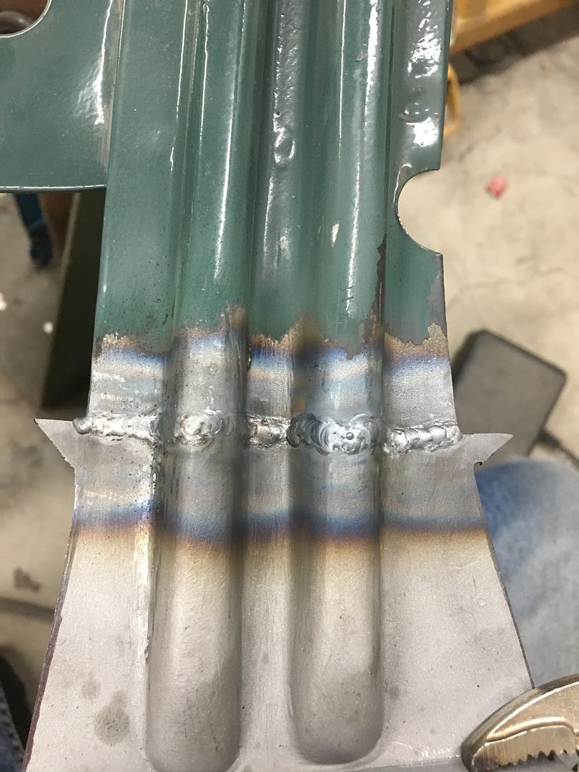
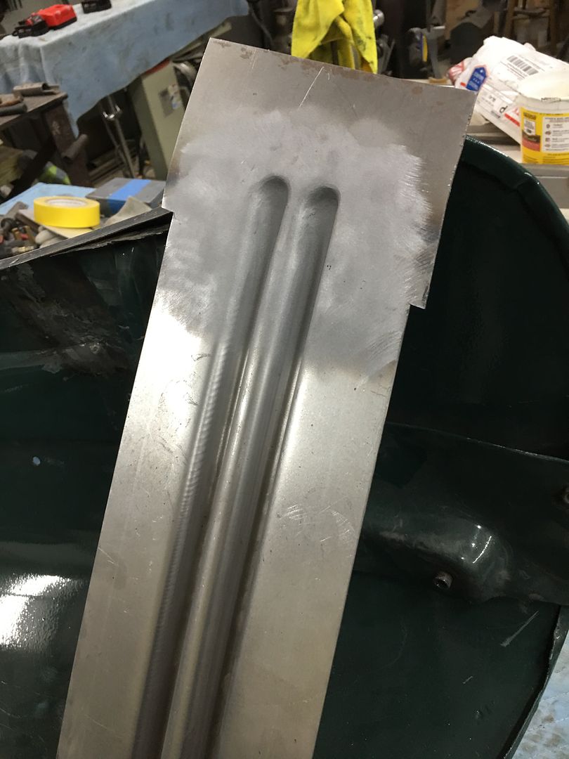
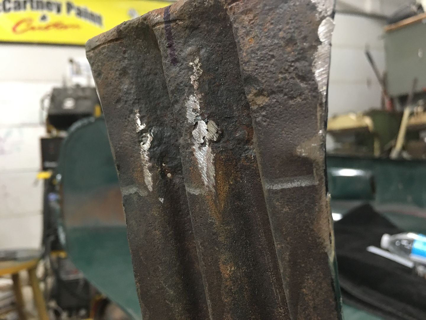
Welds cleaned up and end angles compared..
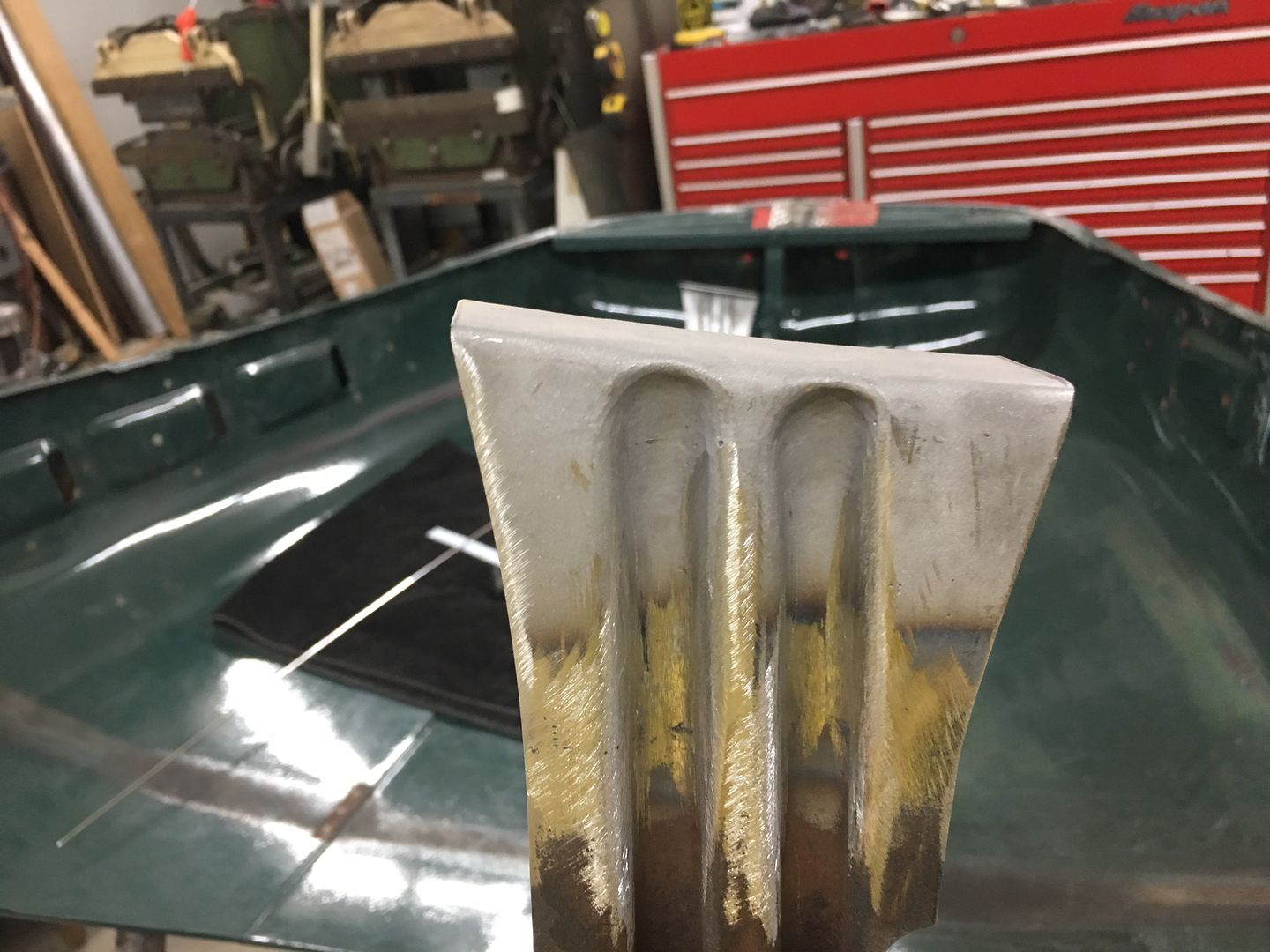
Now we can get back to straightening sheet metal..
Comment
-
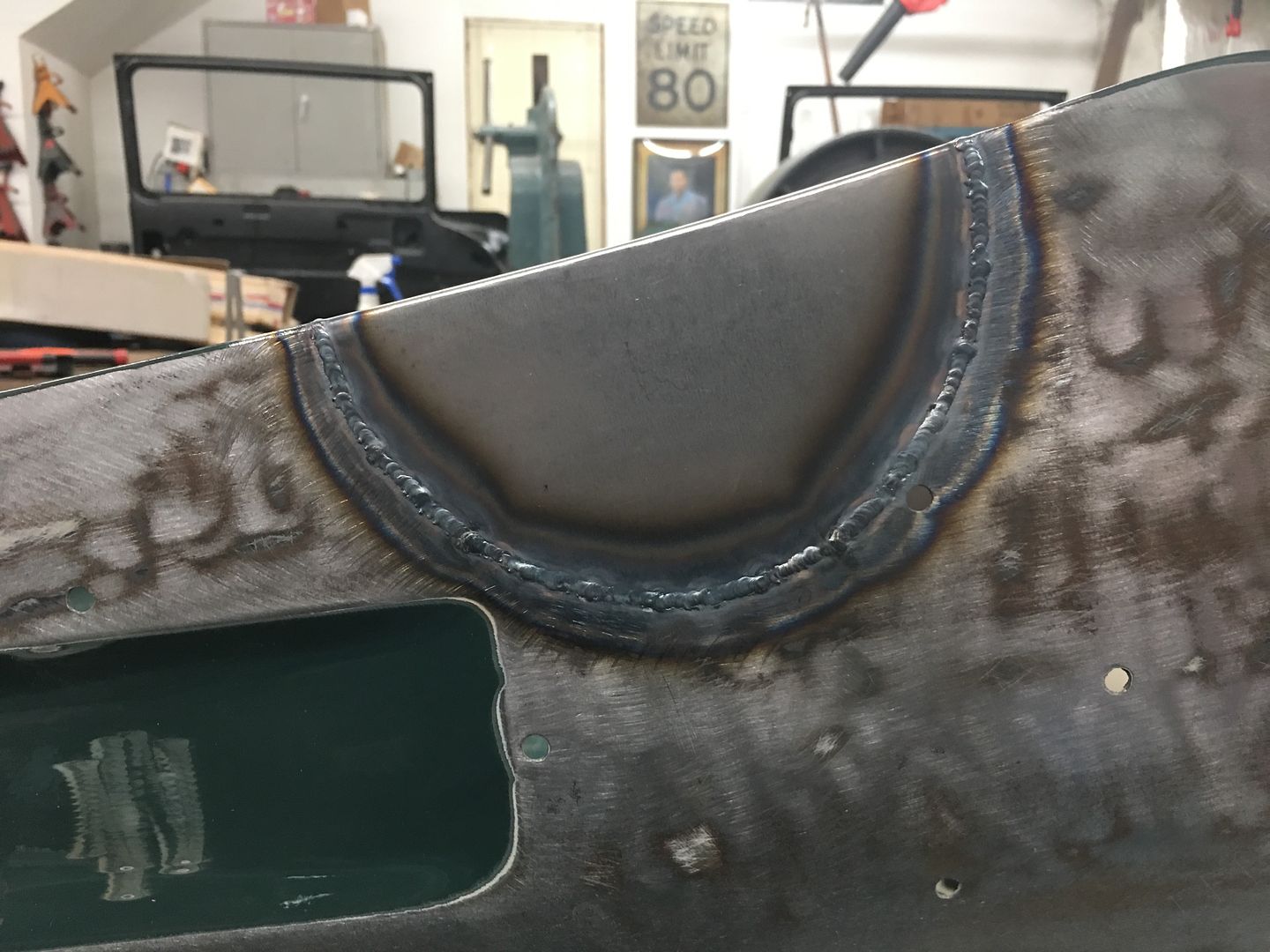
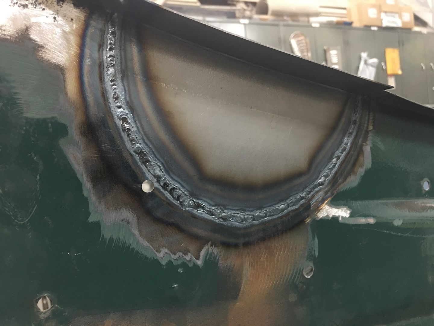
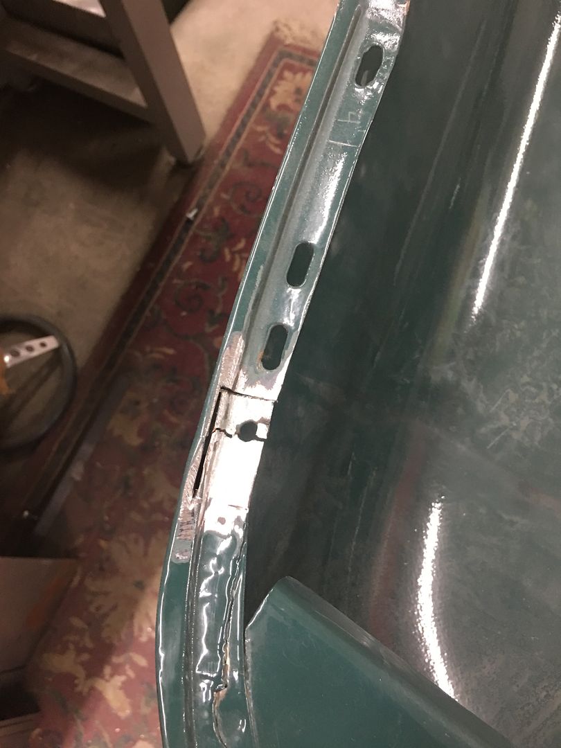
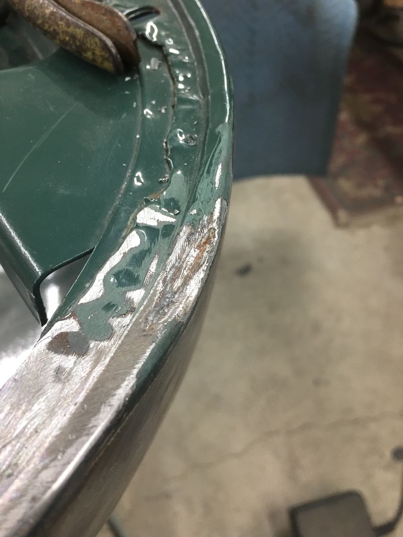
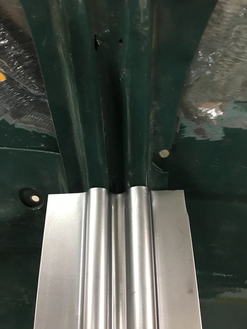
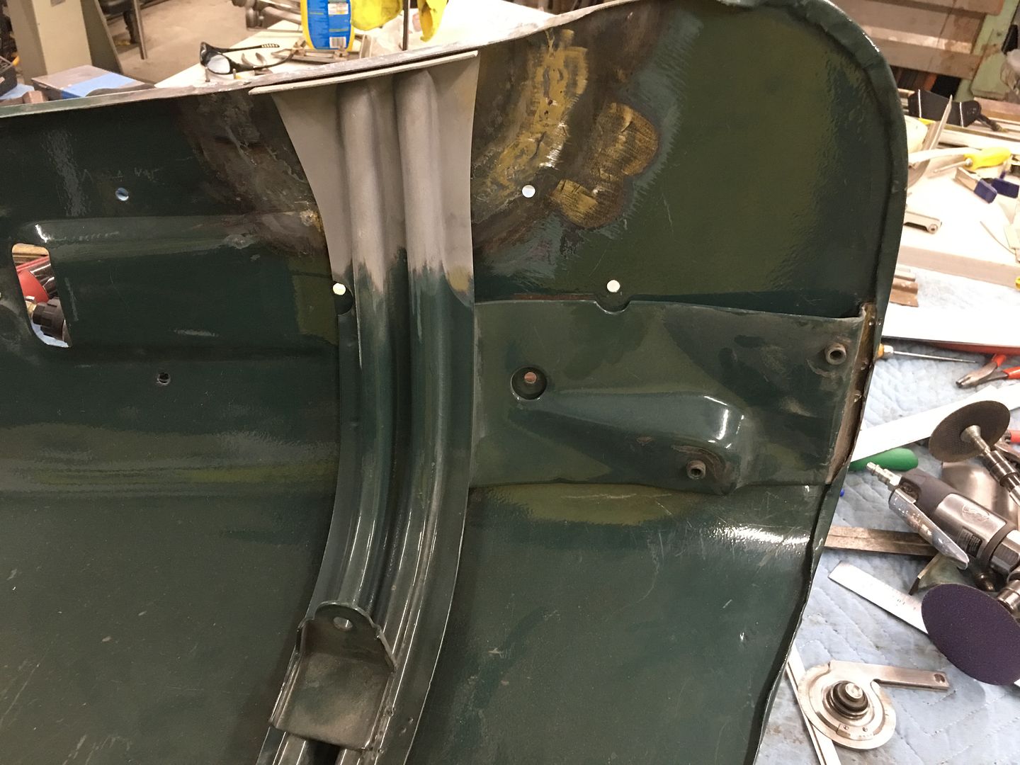
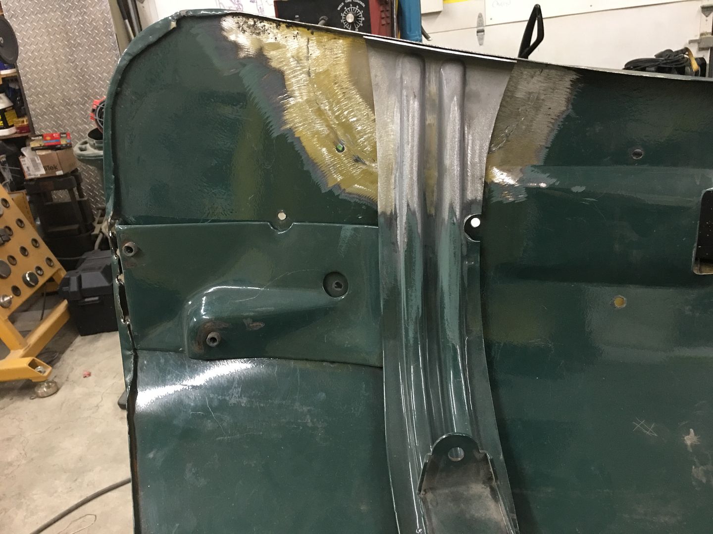
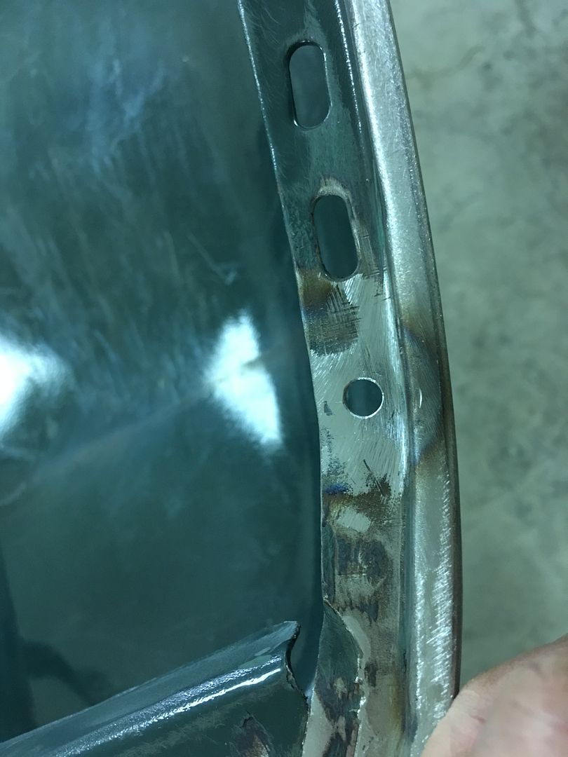
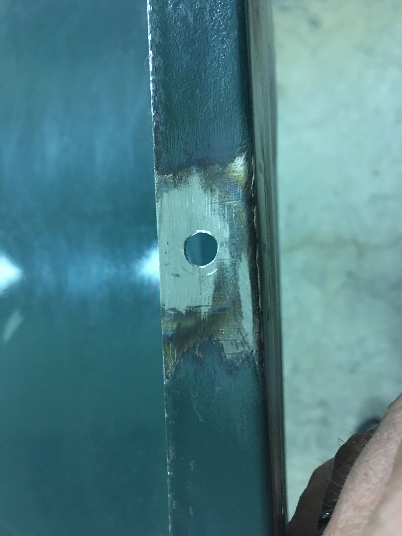
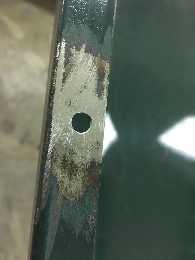
We have a few more spots to fix from cracking and fatigue, namely the holes on the underside for the rubber hood bumpers. We've already repaired three, and from the looks of it, need to take care of the remaining three..
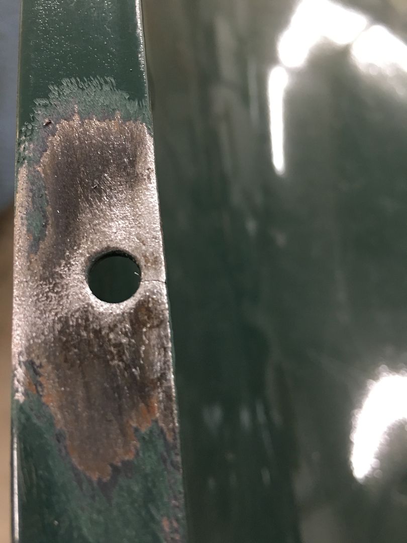
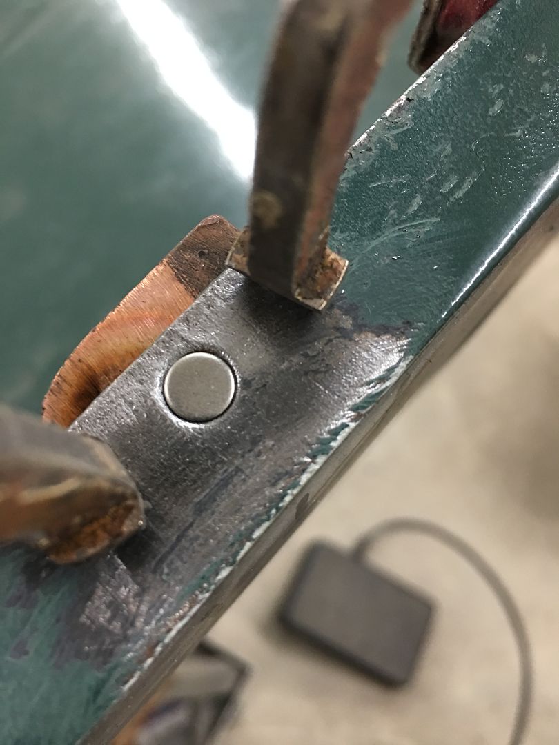
18 Gauge x 1/4" plugs were TIG welded in to fill the existing holes, and a copper backer gives us a bit of a heat sink so the cracks/fatigued areas don't blow a big hole on us..
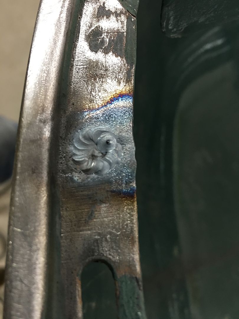
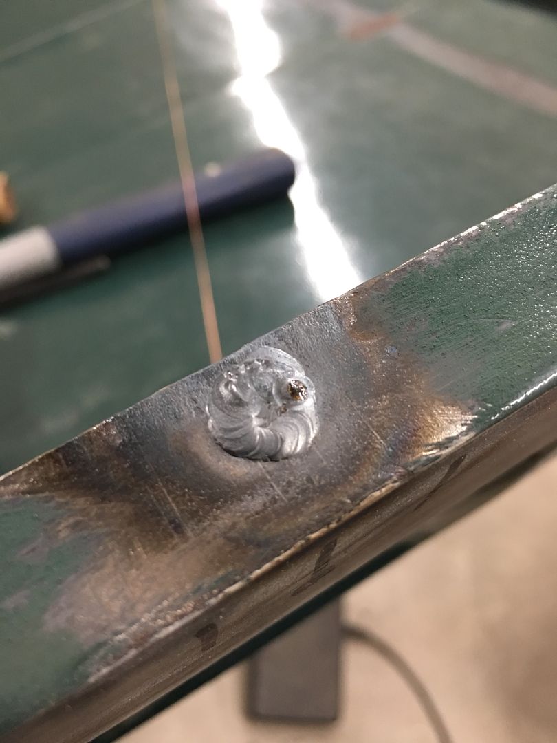
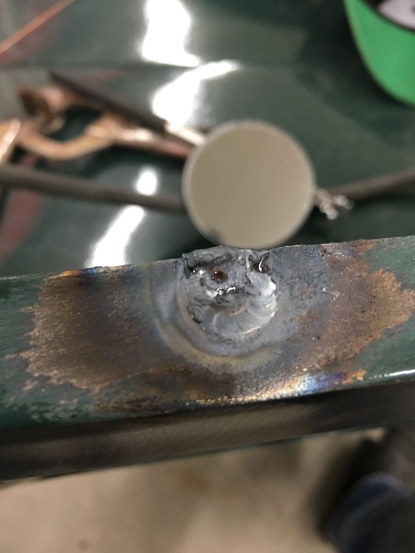
Welds were dressed on both sides of the sheet metal, and new holes drilled slightly in farther from the edge to help slow down the reappearance of cracks.
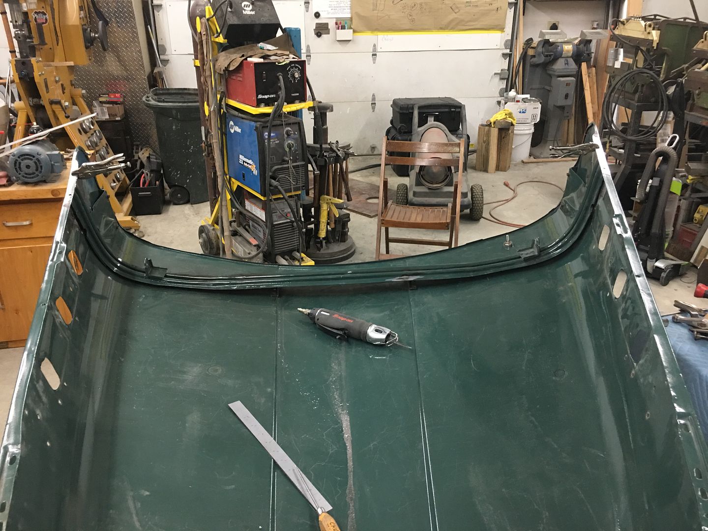
Next, I'm sure everyone has seen how these hoods can oil can, show low spots, and try to flop around while driving down the road. Part of that is abuse over the years, fatigue, etc. Any low spots invariably result in a loss of support of the hood and will show oil cans or loose areas.
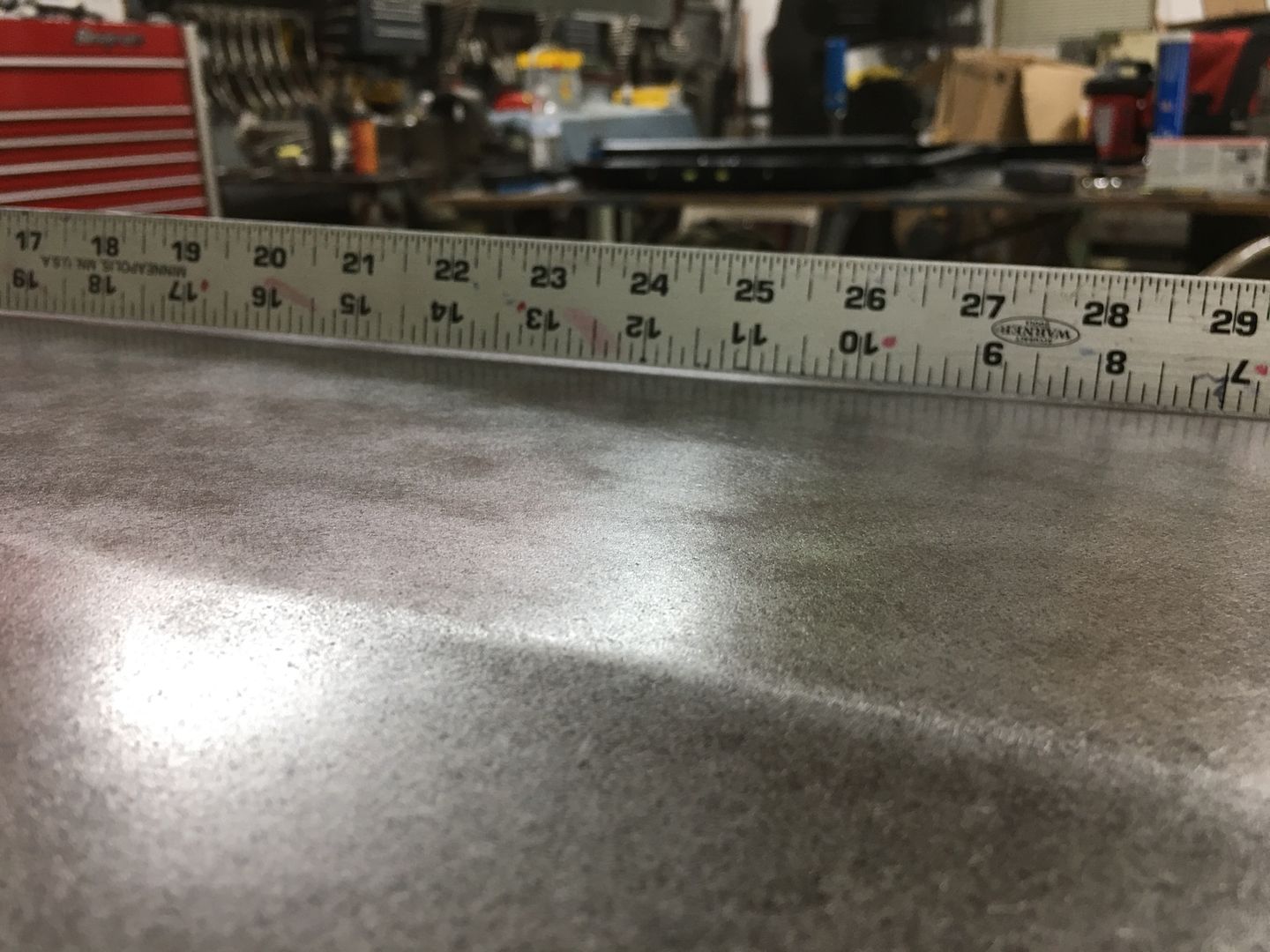
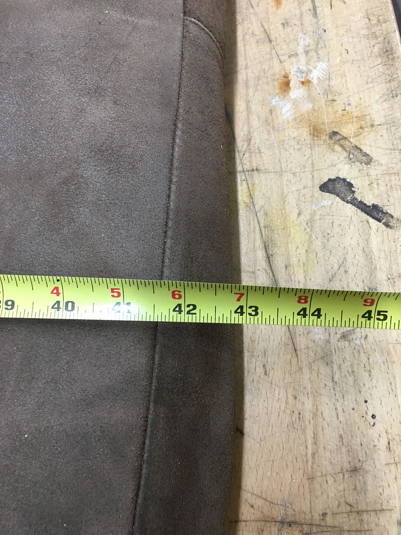
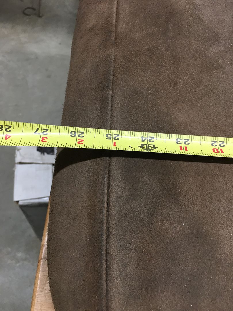
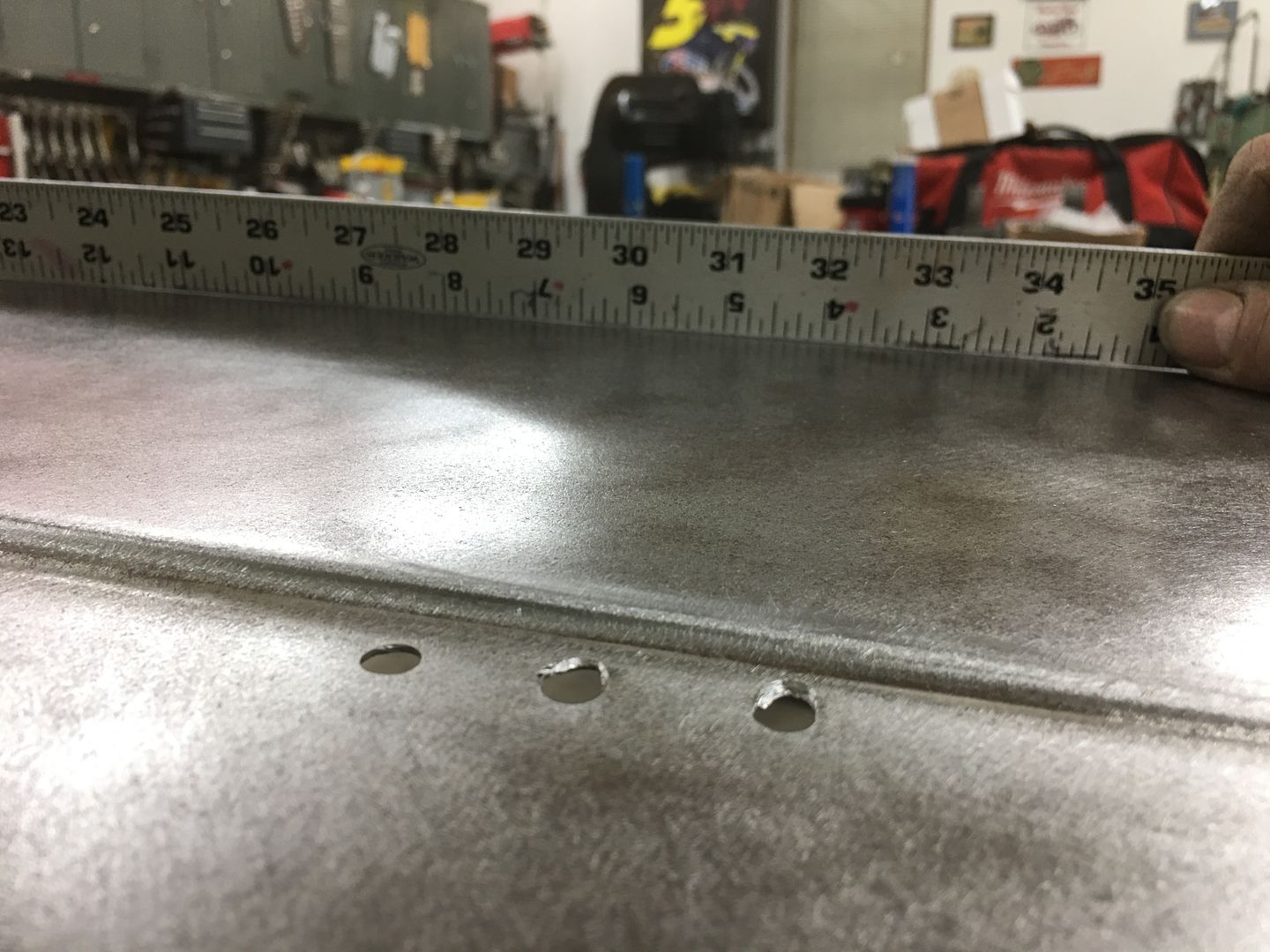
A good tool to check the crown of the hood is a long straight edge in the form of a 36" rule. If you don't have one, most hardware stores sell aluminum flat bar for a few dollars that will make a good profile template. For this style hood, lows are bad, straight is better, and a slight crown in the center crease along the entire length of the "flat" area of the hood is optimal.. This gives the support to help eliminate those oil cans and floppy hoods.
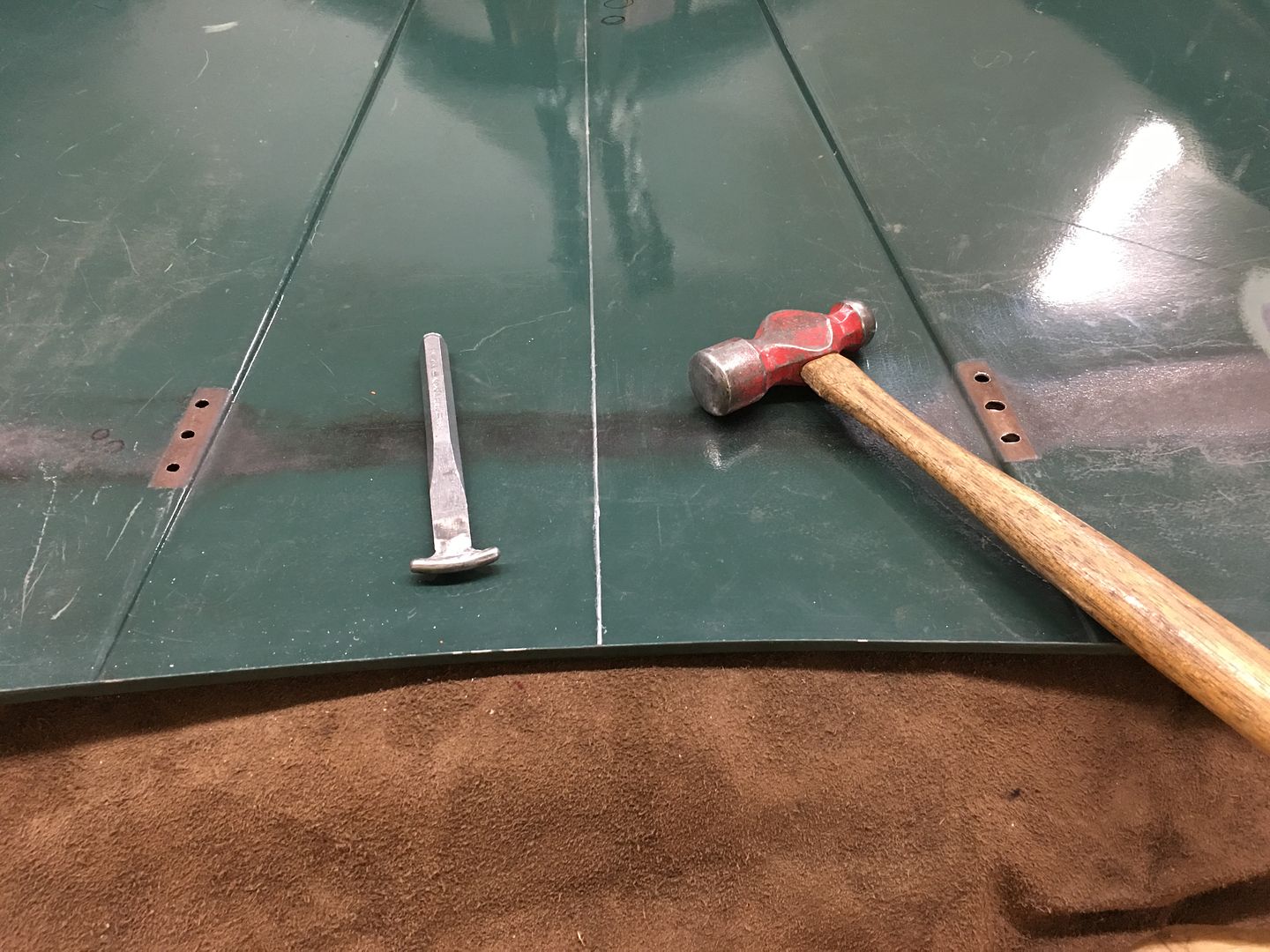
When we started there was an obvious area about 12" forward of the rear edge, dead center, that appears low, and was easily pushed downward. In order to better define the center crease and provide the support needed, we will use a sand bag (a rather large one) and lightly hammer from the bottom side into said bag with a purpose built "punch".
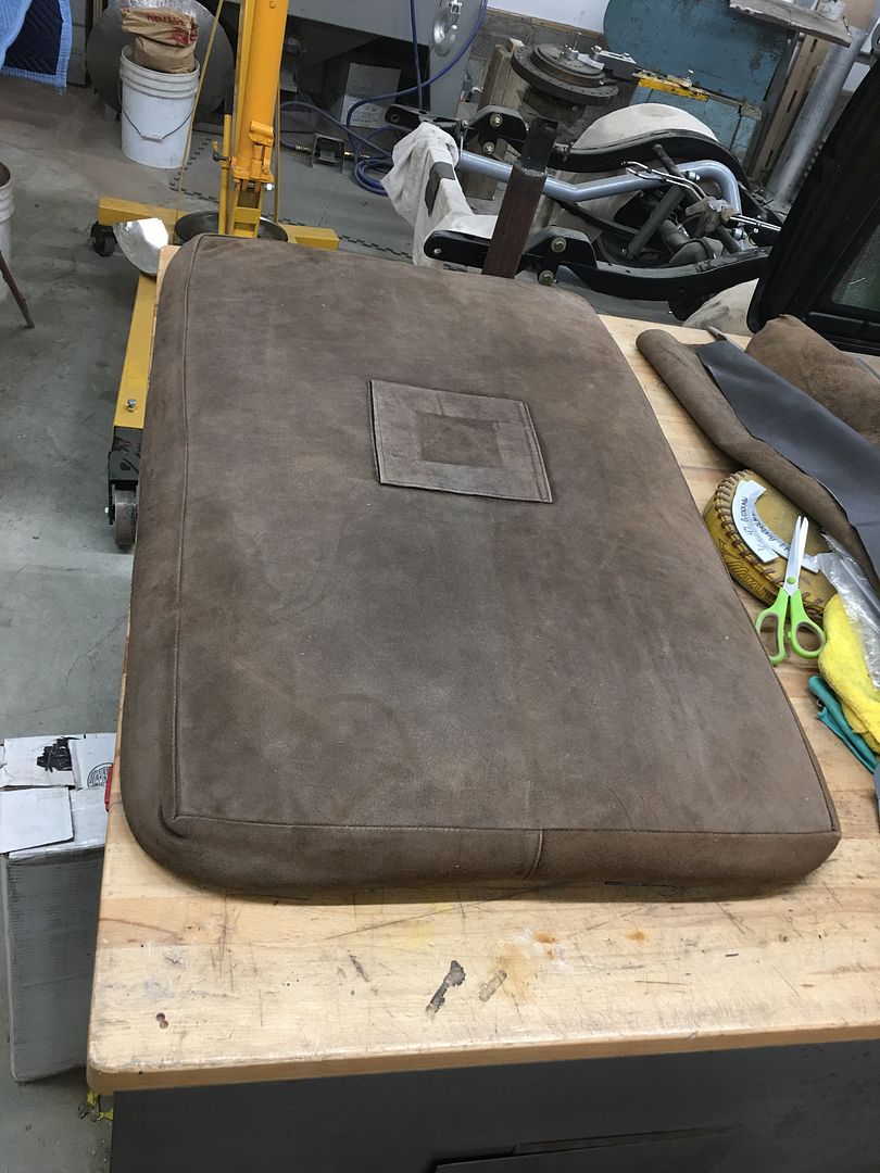
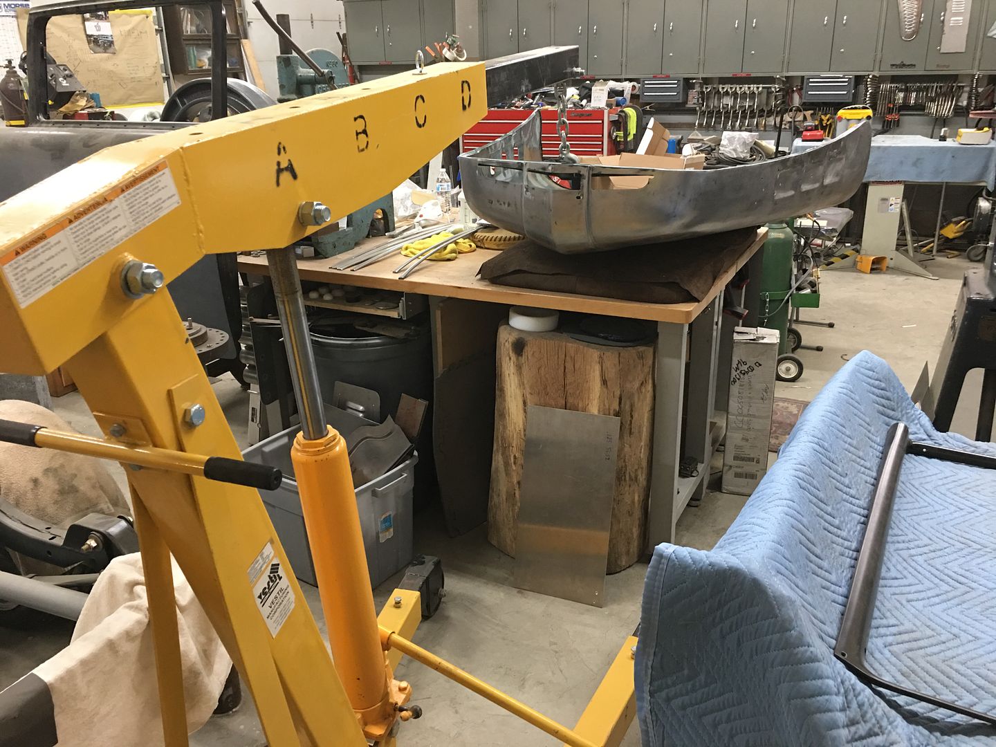
In order to keep the back portion of the hood down against the bag for support, we used our latest "metalshaping" tool to hold the front of the hood up, an engine hoist..
A reference mark is used on the inside, measured and centered...
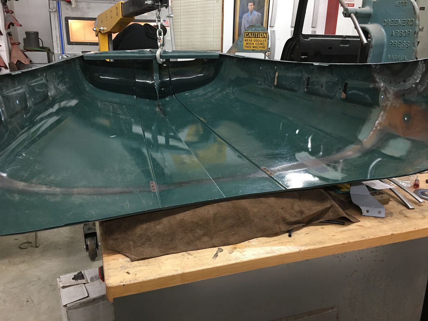
The crease was checked for low spots prior, and the bottom marked. The "punch" is dragged along the centerline and tapped as you go. Flip the hood over, check crown, remark as needed, repeat. We got to a good straight/slight crown and the oil can disappeared. Pushing along the entire center crease was a nice tight support now..
So if you are having issue with your hood, I would suggest first checking your center crease.
Comment


Comment