Announcement

Collapse
No announcement yet.

Can a caveman do DIY EFI? Nothing ventured, nothing gained...

Collapse
X
 
  • Filter
  • Time
  • Show
Clear All
new posts

  • #46
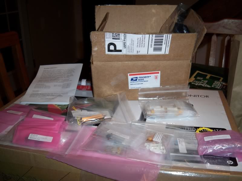
    Well, I finally had a bit of spare time to spend with the MegaSquirt that Santa brought. Its a little intimidating when first opening the box and seeing the barage of teeny-tiny bits that go into these things, but a little reading in the MegaManual and a couple of "dry-runs" generate a lot of confidence. The DIY guys do a great job of making this process as simple as it can be.

    So here is what greets you upon first diving in.


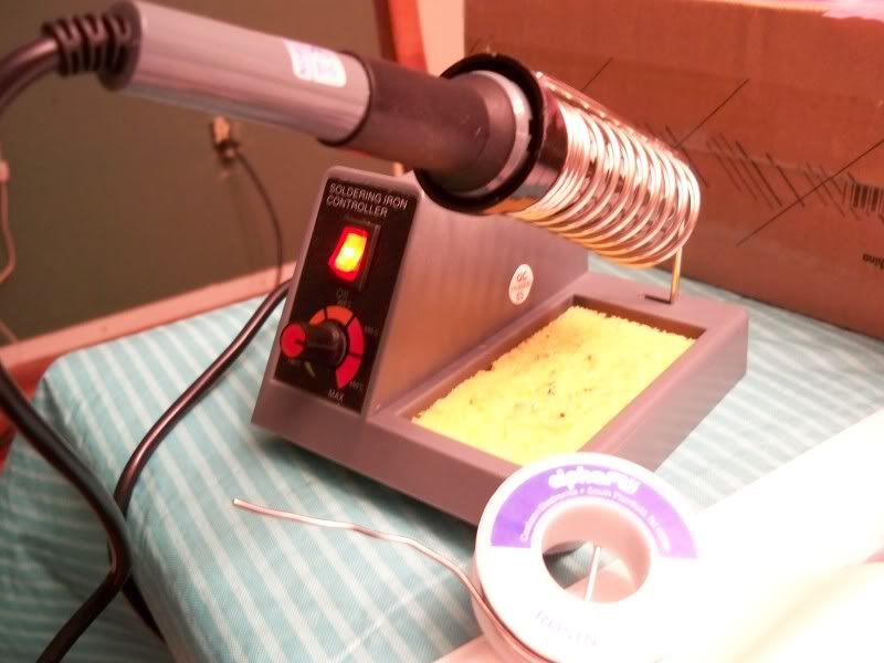
    I decided to splurge and treat myself to a new soldering iron, as my old Weller iron from 1982 has earned its retirement many times over. Has it really been 30 years since Grandpa gave me that Weller for Christmas? Yikes.....
    Anyway, here is the replacement. Nice to have a stand and wipe pad, the temperature adjustablity is nice too. This bad boy set me back a whopping $16


    I set up shop on the dining room table (wife was a little later than usual getting home last night, Suprise Honey!) Nothing fancy, just ran an extension cord and used the printed-off Megamanual for a work surface. Nothing but the best here at Club Med. Kids were intrigued too.

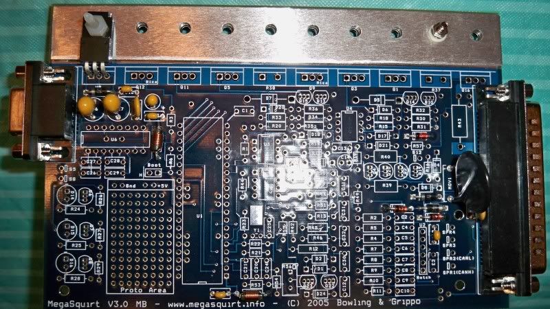
    I got into the groove pretty quickly and in 1 1/2 hours I had this to show for my time. Found it nice and relaxing too, good change of pace from the normal havoc.


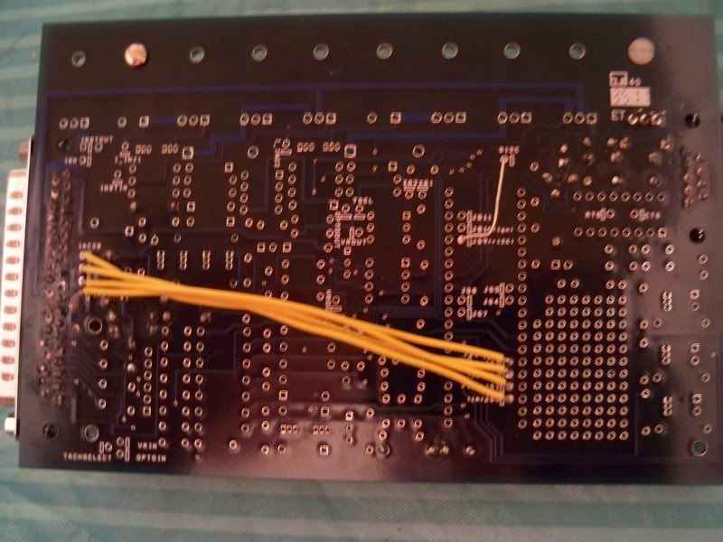
    And the hairy side. I decided not to trim as I went, will just do that all at once as I clear a stage.


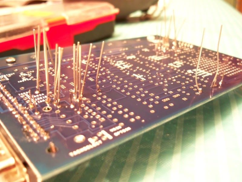
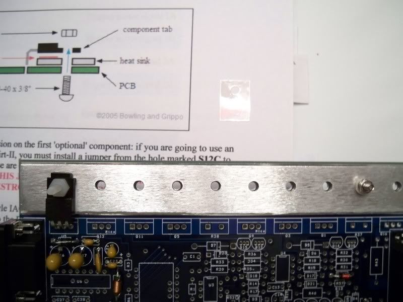
    Found a good stopping point and a question. Each packet of fasteners for the heat sink has one of these little clear plastic shim pieces with a hole in it, but the manual doesn't address them. The picture in the manual doesn't show it either.

    Should I just consider them "extra" parts or would it be a good idea to incorporate them? Shim piece is on paper just above PCB....what is this piece normally if I don't need it? Just curious, that's the whole point of this project for me anyways, learning new stuff.

    And just to be sure - no heat sink grease between the PCB and aluminum heat sink itself? That's how I read the manual, though it didn't actually say.

    Last edited by STINEY; January 27, 2012, 12:23 PM.
    Of all the paths you take in life - make sure a few of them are dirt.

    Comment


    • #47
      Way to go Stiney!! this is a *real* megasquirt assembly (not a plug-n-play).

      On the heat sinks, I only use grease and isolators on the few items that need physical insulation away from the heat sink's aluminum. I thought in the instructions it shows you which ones require that and which don't? It's definitely required for those that you don't want grounding out on the heat sink though.

      If Matt doesn't chime in, I can look at my docs at home tonight after work.
      www.realtuners.com - catch the RealTuners Radio Podcast on Youtube, Facebook, iTunes, and anywhere else podcasts are distributed!

      Comment


      • #48
        The mica insulator is used in cases where you're mounting a metal backed transistor to a heat sink, and you need to insulate it electrically because of that specific circuit design. If the part is not shown in the instructions, you don't need it. For example if the part is plastic coated, or if it's supposed to have the heat tab connected electrically to the heat sink.

        The goo needs to go between the part that gets hot (the transistor) and the part that cools it (the heat sink), no need for it on the PCB.
        My fabulous web page

        "If it don't go, chrome it!" --Stroker McGurk

        Comment


        • #49
          This particular item was indeed plastic coated. I didn't read far enough ahead to see if they are all plastic coated or not, that sounds like a good project for tonight though.

          The metal part of the board under the sink is what threw me - made me wonder if it should have goo there in order to help dissipate heat from the board itself. If there were no metal under the sink I would never have wondered about goo there.

          On a side note I am also finally learning about how to take decent pictures of close up stuff. Its amazing how many cool settings this little Kodak V1073 has.....but I am easily amused too.
          Of all the paths you take in life - make sure a few of them are dirt.

          Comment


          • #50
            I believe the metal strip was originally meant to be the heat sink, but it turned out they needed a bit more heat sinking than the strip could provide. It does not transfer heat from the PCB to the heat sink.

            Comment


            • #51
              On the plastic vs metal screws. I vaguely recall one being specified for each. In any case, here is a picture of my MSII, 35,000+ miles logged on it set up this way so something must of been done right =P


              A refresher of my intimidating work station Dang this picture was taken in February 2008, almost 4 years ago. Didn't get it running on the MS until around October though.
              Escaped on a technicality.

              Comment


              • #52
                Here's the backside. Ignore the arrows, they were pointing to the ignition jumpers. The Black and White wires are the 4 wires for the IAC valve and mine has the MapDaddy board on it where the MAP sensor goes.
                Last edited by TheSilverBuick; January 27, 2012, 01:44 PM.
                Escaped on a technicality.

                Comment


                • #53
                  Did a little more tonight. Just some options to do (or not to do?) before checking the power supply.

                  I assume that I should go ahead and jumper for the IAC since that is a part of the TBI I will eventually be using?
                  I guess my question is, is there any reason why I should NOT jumper them at this time, for instance if I run it as a data logger for a while first before doing fuel or ignition?

                  Along those same lines, what about the JS10 to IGN (or IGBTIN, with IGBTOUT jumpered to IGN)?
                  I will probably end up using the HEI pickup to signal the MSII, and MSII to fire a MSD, but first may just run the HEI by itself for simplicty. What is this jumper actually doing?

                  And will I be using CAN communication between boards? Should I jumper JS6 to SPR1/CANH and also JS8 to SPR2/CANL?

                  Last edited by STINEY; January 27, 2012, 06:57 PM.
                  Of all the paths you take in life - make sure a few of them are dirt.

                  Comment


                  • #54
                    The only real reason not to use the IAC in my opinion is if you need those pins for other outputs. As for the ignition, just set all the Jumpers for the VR stuff.
                    Escaped on a technicality.

                    Comment


                    • #55
                      Thanks Randall.

                      Me being a caveman and all, they lost me on the CAN communication between boards thing. Is there a laymans explanation of this?
                      Of all the paths you take in life - make sure a few of them are dirt.

                      Comment


                      • #56
                        Originally posted by STINEY View Post
                        Thanks Randall.

                        Me being a caveman and all, they lost me on the CAN communication between boards thing. Is there a laymans explanation of this?
                        I never done it, nor looked into it. What other board are you linking into, the transmission one?
                        Escaped on a technicality.

                        Comment


                        • #57
                          Beats me.....guess no other board. That there is my answer though, skip the CAN jumper stuff for my purposes.

                          Learning, learning, learning.
                          Of all the paths you take in life - make sure a few of them are dirt.

                          Comment


                          • #58
                            Yup, skip it!
                            Escaped on a technicality.

                            Comment


                            • #59
                              From careful scrutiny of the manual (and hopping all over, from HEI control to MS control of MSD to direct control of a coil) it sounds like where I want to end up eventually is direct control of a MSD box. And that would mean jumpering JS10 to IGBTIN with IGBTOUT jumpered to IGN.

                              I get that. It makes sense at this point.

                              But what I'm unsure of is - since I plan on doing fuel first and ign later, should I leave JS10 to IGBTIN unjumpered until I do ign control? Or can I go ahead and jumper it now? What is the ramifications of either?
                              Of all the paths you take in life - make sure a few of them are dirt.

                              Comment


                              • #60
                                For well over a year I had the pick up wire hooked right to the HEI pickup coil and the spark output wire hooked to the points wire of the MSD box. I'm sure you can hook it up exactly the same way and just hook the tach input signal up to the Tach port of the HEI and leave the output wire unhooked to run fuel only. So jumper it now?
                                Escaped on a technicality.

                                Comment

                                Working...
                                X