 Tweet
Tweet
The alignment looks fine. Get the sensor as close to the wheel as safely practical - our rule of thumb is a standard business card width or 0.040" is about right.
-
-
Looks OK to me, but be prepared to play with the airgap. I would run the MS in VR tach input mode (ask if you need to know how to set that up, it involves potentiometer adjustment).
I usually end up with them at anywhere between .034" and .050" gap.www.realtuners.com - catch the RealTuners Radio Podcast on Youtube, Facebook, iTunes, and anywhere else podcasts are distributed!Comment
-
It would be easy enough to weld a tab to the side of that 90 bend to triangulate it and stiffen it up quite a bit, if vibration ends up being an issue as is.There's always something new to learn.Comment
-
Thanks guys, I will reset the gap. Have been running it with the VR circuit with the HEI dist. So hopefully it will be easy switch I am sure help will be needed when first testing it outComment
-
My GM LS1 Sensor likes to be closer, .025-.030 and there is a difference between small gap changes, not sure why.
Watch out for the wheel to crack at the welds. I had one toss a chunk at the top of 1st gear. Serious oh sh*t moment.Drag Week 2006 & 2012 - Winner Street Race Big Block Naturally Aspirated - R/U 2007 Broke DW '05 and Drag Weekend '15 Coincidence?Comment
-
Cracking the wheel doesn't sound good. Should I weld the wheel completely around the circumference?Comment
-
Originally posted by seanm View Post
I think Bill's cracked because it was press-fit very tight? I've never ever seen an EDIS wheel crack and know guys using it up to 9200rpm with hundreds of passes. I don't think it should be a concern in your case unless you go nuts on the press fit?www.realtuners.com - catch the RealTuners Radio Podcast on Youtube, Facebook, iTunes, and anywhere else podcasts are distributed!Comment
-
I don't have a good answer to the question as it was version 2 that fragged and I didn't build that one. v1 was 360 mig welded by yours truly and worked fine using a JY Ford wheel opened up on lathe to to slip onto the damper spacer. A change in crankshaft snout with a new crank required a new balancer and another wheel, this one a parts counter Ford piece, same P/n. it was TIG welded by a pro who worked with my machine shop and I'm not sure how tight the fit was at time of assembly. V3 was a water jet cut copy of the Ford part made with cold rolled plate and is bolted the damper, no welding, so far so good. I suspect it wasn't a press fit issue rather it was localized heat cracking from the TIG process which were very small stitch welds on the powdered metal factory part. But, that is just my speculation.Originally posted by dieselgeek View PostDrag Week 2006 & 2012 - Winner Street Race Big Block Naturally Aspirated - R/U 2007 Broke DW '05 and Drag Weekend '15 Coincidence?Comment
-
Well that is a conundrum. Maybe using silicon bronze to braze it might work. There is no slip or press fit on this wheel. The welds hold it all.
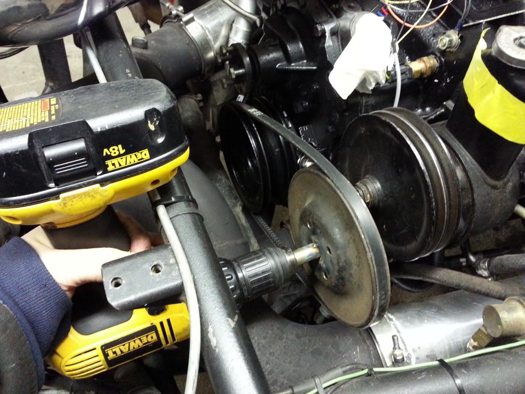
Did some quick checks today. Set the crank pulley to "freewheel" on the crank hub. Then used a cordless drill with a belt and another pulley to spin it. The damn hillbilly contraption worked LOL. Max rpm read 4300rpm. Still learning the trigger logger, but it looked right to me so far.
Comment
-
Nice test!Escaped on a technicality.Comment
-
That's a great test to make sure your trigger settings are right. The VR circuit might still need to be adjusted to account for electrical noise during cranking and running.Comment
-
Very cool test rig Sean!
How did you hone the hub to freewheel on the crank? I took a piece of keystock crudely cut down to be somewhat level with the ID of the hub, and used a stone brake hone to open mine up.
(For you non-Cadillac guys, these hubs use a crazy-tight interference fit from the factory with no bolt. They DID however, get a factory installed CORK to plug the threads)Of all the paths you take in life - make sure a few of them are dirt.Comment
-
Just the pulley free wheels the hub stays stationary. Welded some tabs on the crank hub washer that pushes lightly against the crank pulley then sprayed it with wd40 to let it spin fairly easily.
Not sure if it is reading the correct rpm. Didn't think the drill would spin fast enough for anything much above idle.Comment
-
We used a bench grinder as a crank trigger dyno one time when were chasing an intermittent crank signal on an MS setup. Buddy Brian figured out how to mount the trigger wheel to the grinder shaft and da 'Geek wired up the portable 'scope. Once we found the cracked connection between the wire and female tab inside the weather pack connector it would read a nice clean square wave down to 10 or 20 rpm all the way up the grinders rated speed which allowed to somewhat verify the rpm output accuracy. MS 3 makes all this so much easier.
Your test setup is genius.Drag Week 2006 & 2012 - Winner Street Race Big Block Naturally Aspirated - R/U 2007 Broke DW '05 and Drag Weekend '15 Coincidence?Comment
-
Regarding wheel failure, this was V1. BBF's use a spacer between the damper and the crank gear. There was enough space to put the wheel and the sensor behind damper and keep the pulley assembly the same length. Never had an issue.
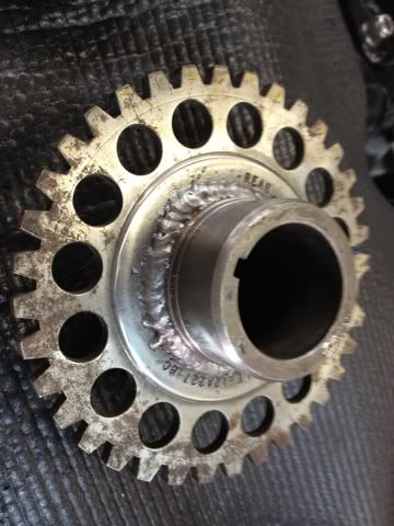
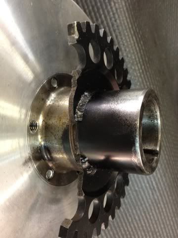
This was V2. The Innovators West damper has an integrated hub due to the shorter Boss 429 style snout on the Bryant crank. You can see how it was welded to the hub. It was fine until it wasn't and that piece flew off and the engine quit light turning of a light switch at the top of 1st gear at Famoso. The flying chuck made one dent in the oil pump mount and left the car without causing other damage. I was lucky
I think if I saw the picture correctly you have the ring that goes on the outer OD of the pulley. With much lower mass at any one point and it should be fine.Drag Week 2006 & 2012 - Winner Street Race Big Block Naturally Aspirated - R/U 2007 Broke DW '05 and Drag Weekend '15 Coincidence?Comment
Comment