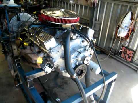
Neat setup! You certainly don't lack for imagination - or effort.
At EPA we had accoustical steel walls - basically a sandwich of perforated sheet metal (maybe 18 ga. as a guess) and that sort of fiberous insulation that looks sort of like Beaverboard. The steel sheets were perforated on one side and solid on the flip side so there were never 2 perforated sheets back to back. They were installed with the perforated side in (toward the engine) on one panel and the next panel was installed with the solid panel in.
These were pretty stout but even then we'd see BIG dents from fairly minor causes. Those panels were stout enough to catch a driveshaft but we had a big shield over the shafts that was a split piece of 1/4" wall tubing of about 12" in diameter with wooden blocks in them to guide the shaft if it came loose. We didn't lose them often but we did from time to time.
NO ONE went into the cell with the engine under load. There were times when it was deemed necessary due to the need to diagnose a malfunction or some such and then we implemented a pretty extreme protocol with a spotter, a dyno operator, and we had to notify the safety office.
Dynos are fun and very useful but there's a possibility of getting hurt badly so you need to assume that the worst CAN happen. Like firearms, safe if used with respect.
Be sure to keep the water clean and at a constant temp. The cal will vary depending on the viscosity of the transfer fluid and you'll chase a moving target. You can't calibrate a load cell but you should be able to calibrate your readout. Set the deadweights (known moment arm length, known weight = known readout ft/lb) and tell the computer what that value is. For example, you have 100 lbs. on a 1 foot arm so the ft/lb should read 100. If it reads 105 (or 97 or whatever) on the computer just tell it that this is 100. Keep doing that thruout your range of weights and you're there. If you want to get fussy you can develop a formula that lets the 'puter figure out the error at every point on the curve so it can fix it on the fly. At EPA we had a maximum error beyond which you had to replace the load cell and start over - rarely happened. Load cells pretty much work or they don't. If you want to get REALLY sexy you might look for a rotary transformer inline load cell so you get the results without the time errors built into reading case torque which is what you have now. LOTS more money (of course!).
We had our weights calibrated from time to time (I think it was every 10 years). In Michigan the only NIST-traceable source we had was the State Bureau of Weights and Measures. As a governmental agency they did it as a favor - no clue if they'd do that for an individual. Remember, each part of the system needs cal to keep the results knowable - the weights, the calibration arm length, the tach, etc, etc. You, of course, can wander from this but I want you to know the maximum way this testing is done. You should see what it takes to get an SAE certified horsepower reading!
PM Jim (Squirrel) and see if he can send you a copy of the article. As the author I don't own it (Primedia bought it when they paid me for it) but evidently a private party can e-source it to someone else for individual use. Jim's at a robot competition this weekend so don't expect to hear back from him for a couple of days.
Dan
Last edited by DanStokes; March 3, 2012, 05:41 PM.
I have an arm that inserts into the torque arm. It has a vertical bar to stack my rusty barbells on it. They obviously aren't traceable but work for this. The weights I have vary between 3 and 25 lbs. I end up with a 28 point cal. Right now I'm just using a linear cal factor that gets me within 4% of reading and 1.4% of full scale of 1000lbs. The load cell I currently have is a 5000lb unit so I may try moving it closer increase resolution. I think I've been seeing some issues from the water heating. I started working on a way to get more water through it. I'll do some research on the viscosity changes caused by temp. I can also log the temp in the brake on some pulls.
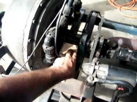
Is the fluid flywheel a torque converter or something completely different? It looks like it could handle a bunch of torque. I wonder how many RPM it could take. I was thinking of modifying a car sized torque converter to see if it would work as a brake once I get some baseline data on an engine.
Not sure. Remember, the absorbing fluid can be oil - there are commercial units that do. They're called "Hydraulic" as opposed to "Hydrokenetic". The higher the viscosity the more power it'll absorb but the better your cooling fluid (usually H2O) needs to be to keep the system stable. My guess is that he used a truck torque converter which seems like it would work better with oil.
Remember to install a magnesium plug on the absorber somewhere. It'll keep the absorber from getting eaten. Maybe you're ahead of me on that.
Dan
Last edited by DanStokes; March 4, 2012, 04:15 PM.
Forgot to mention - our Calibration and Maintenance guys (I never worked on that crew but helped from time to time) fitted small Culligan water conditioners on the inlet cooling water line for the Clayton hydrokenetic chassis dynos. It helped a LOT. Rather than the water softener/salt units, these were the kind you return to Culligan for regeneration. I don't think there is any salt involved. Later on we got a recirculating water system and that saves a TON of water (we had maybe 8 hydrokenetic dynos). Also changed to Horiba flux-vectored AC dynos after the closed water system and they used even less water as the generated power was used to power the building with the excess sold back to the power company.
You can do a closed water system with a big plastic stock tank - they aren't horribly expensive. You want the kind that seals with a lid. Chill the dyno return water thru some sort of heat exchanger (I saw one guy who had a car radiator and sprayed it with a garden hose while under load - crude by effective). The idea is to use the tank as sort of a thermal capacitor to store ambient temp water and supply it to the dyno as needed. The cooling water can then be conditioned with some antifreeze and an appropriate amount of Water Wetter. It keeps the water temp pretty steady.
Dan,
I hadn't thought about installing a sacrificial plug in it yet. I didn't think it'd make it this far. I have been draining it though. I have an 80 gallon tank I might try using. I have the efi installed. I need to plumb the fuel and I'll be ready to make some more pulls.
I think our mag plugs came from Clayton but they may be available from many sources. They were about 1 1/2" long when new and screwed into a maybe 1" NPT bung. They changed them on a regular schedule (maybe monthly) and they were pretty well chewed up when they were pulled. Before we got them on a good maintenance schedule we'd occasionally fail one during a test - EXPENSIVE! But you'll be surprised at how they get eaten.
I got the efi on the motor and fired it on Friday. For some reason it's smoking out the valve covers worse and the exh on decel. Plugs are oil fouled. I flooded it a bit at first. The oil didn't smell like gas but I drained it anyway. I've resisted the urge to buy some new heads for now and am waiting on the valve seals I ordered to arrive. All the heads I want would require a better intake and I don't think there's room for anything taller than the Performer. I'd rather buy heads for the 454 coming up next.
Some more electronics showed up and I now have 8 egt's and two spare thermocouple channels. I'm thinking a thermocouple on the dipstick would be the easiest, but what is the typical method of measuring oil temp? It seems to me that BSFC should be near the top of my list for now. What do you guys think?
Thanks,
Kevin
I don't worry about BSFC especially on a turbo combo. Better to have wideband O2 sensors at least in each collector.
www.realtuners.com - catch the RealTuners Radio Podcast on Youtube, Facebook, iTunes, and anywhere else podcasts are distributed!
I finally got my junk together and made a couple pulls turbo'd and injected. The results are much better. I've reworked my water supply and now have a manual load control valve on my computer cart. Data from the load cell has gotten noisy but I can fix that. Here's the first part throttle no boost pull. I didn't data log.
Here's the second pull I made tonight. The boost started climbing so I shut down early. I ran VE analyzer after the pull. I haven't tried Analyze Live at any kind of load yet. Do you have any idea other than timing why the power is staying flat as boost came up? Also should EGT's be climbing like they did in the first pull?
Good data. Nice clean tach signal. What's with the ignition timing being so advanced? did you get a chance to make sure it's not retarding with increasing RPM?
www.realtuners.com - catch the RealTuners Radio Podcast on Youtube, Facebook, iTunes, and anywhere else podcasts are distributed!
I haven't checked to see if timing is being retarded up top. It's correct down low and likes it that high when I load it at idle. I'll try to check it tonight.
 Tweet
Tweet

Comment