 Tweet
Tweet
Awesome work! The door holder is probably overkill for me but I'll definitely be copying the vice grip ideas. Thanks!
-
-
That door holder rules!Escaped on a technicality.Comment
-
This is for you guys that have to do electrical trouble shooting..... They are test leads with insulation piercing test hooks.... These make testing wires a snap.....


Comment
-
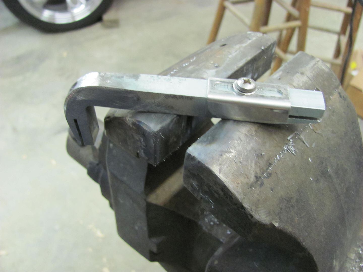
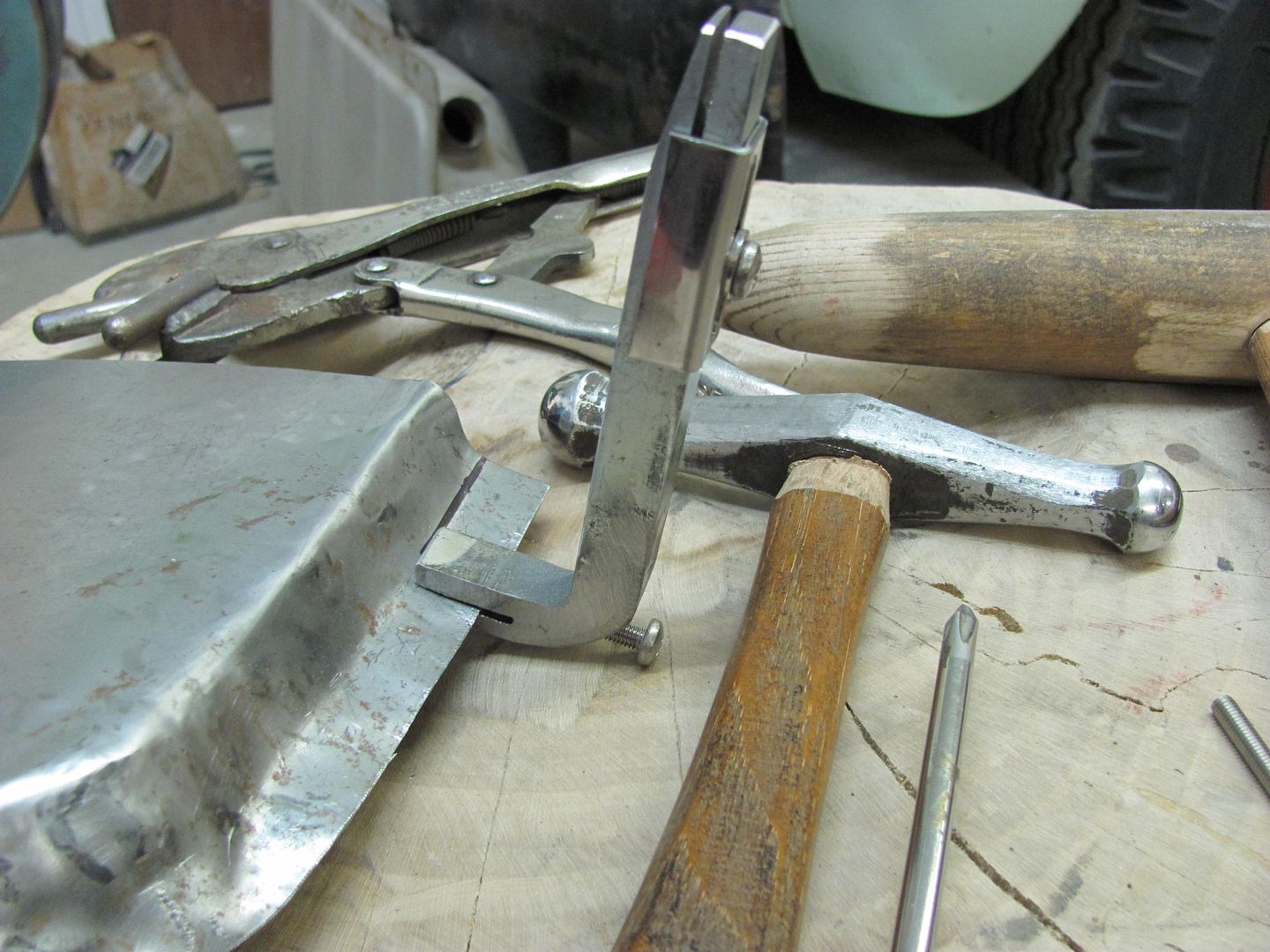
Easily made tool for tipping a flange, such as on a door skin patch....Used some 1/2" key stock, clamped it in the vise and used a rosebud and hammer to bend the 90.
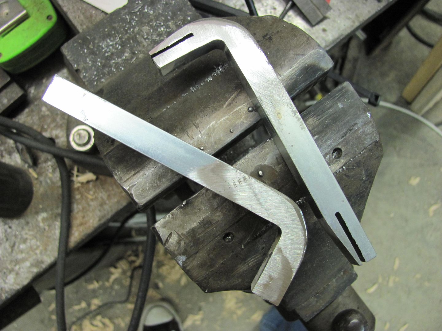
A set screw in the threaded hole will act as a stop for consistent flange width. Should finish it up tomorrow.Comment
-
Now for the whole story....
Credits: (and all that legal stuff) this is a slight variation on a similar tool by Per (Metalman Sweden) and Bill Gibson, as shown on Metalmeet.
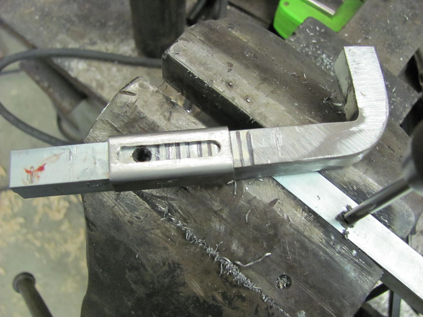
This is a tool for tipping flanges, as one would do on door skins or inner doors, offered as a low buck alternative for those who may only need a one-time/limited use of such a device. I started with 1/2" key stock, which came in a one foot length. The gave me enough material for two, if I ever get to finishing both.
The short leg was marked at about 1-1/2" in, clamped in the vise, heated with a rosebud torch and persuaded to a 90 degree angle with a hammer.
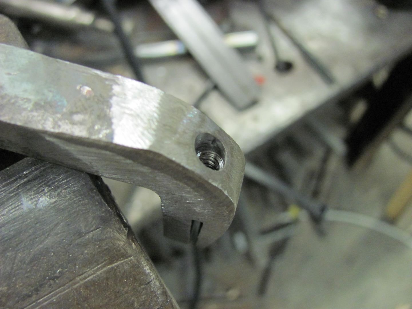
Used the bandsaw to cut some notches about an inch in. These should be about twice the thickness (or so) of the metal you plan on using, to allow some free play in using the device.
The short end had a #21 hole drilled through the slot and tapped for 10-32 screw to use as a "distance stop". The long end would use a tapped hole to secure a separate stop device.
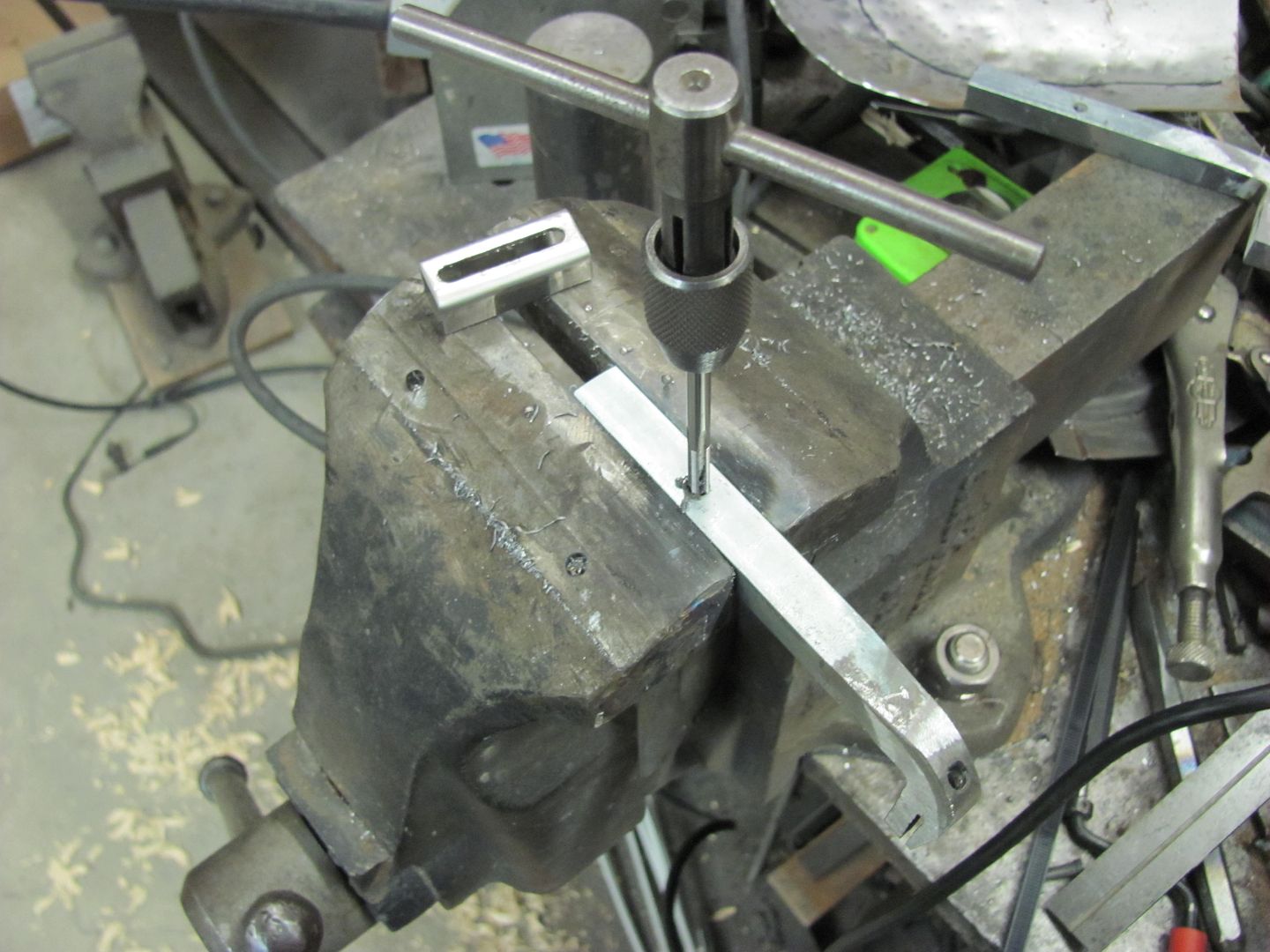
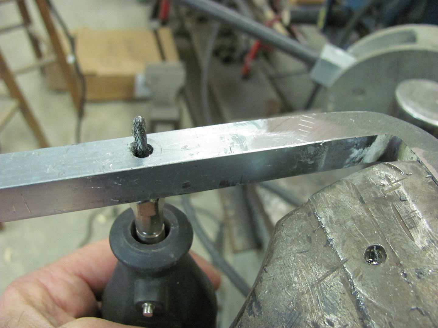
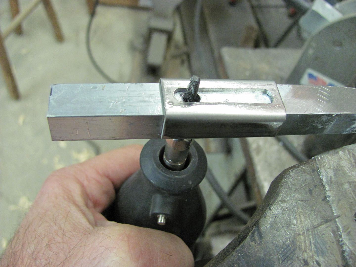
The second tool was used as a drilling/milling fixture for making the stop device for the long arm. A tight clearance hole was drilled centered on the 1/2 stock, a cap device was bent to fit snugly and come down the sides past the slot, and it was clamped in the vise at the various marks shown to start the slot. Although I neglected in-process pictures of this step, follow along with the descriptions.
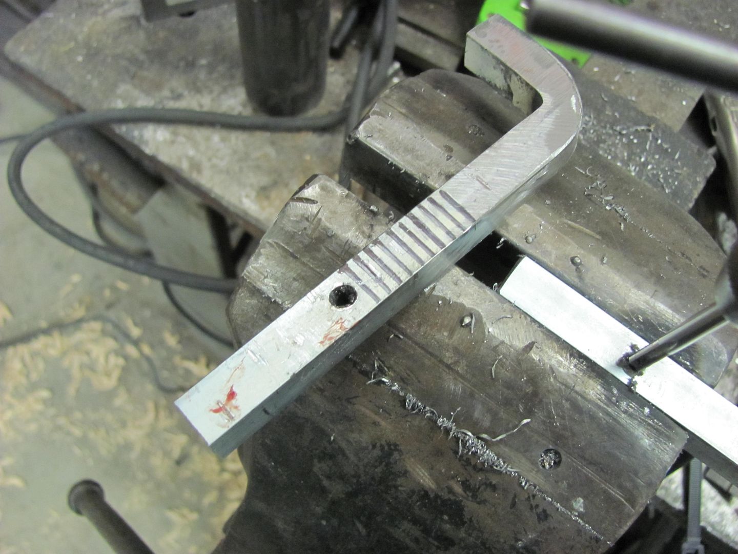
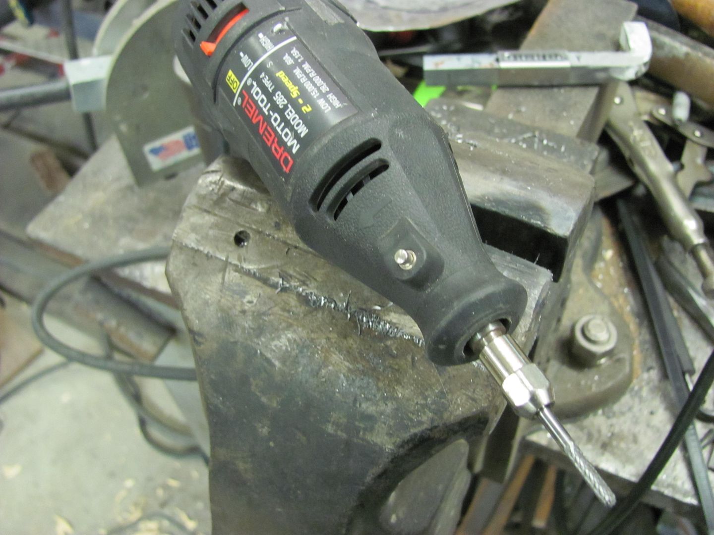
Then, to clean between the holes, a dremel with an 1/8 diameter ball end burr was used as a "milling" bit. Be sure to extend a good (safe) amount of the smooth side, so the cutter has less tendency to eat away at the drill guide. Then with the dremel bit inserted, place stop device over and work back and forth to open up the slotted hole. Repeat for other side of the slot, as this cutter is considerably smaller than our clearance hole.
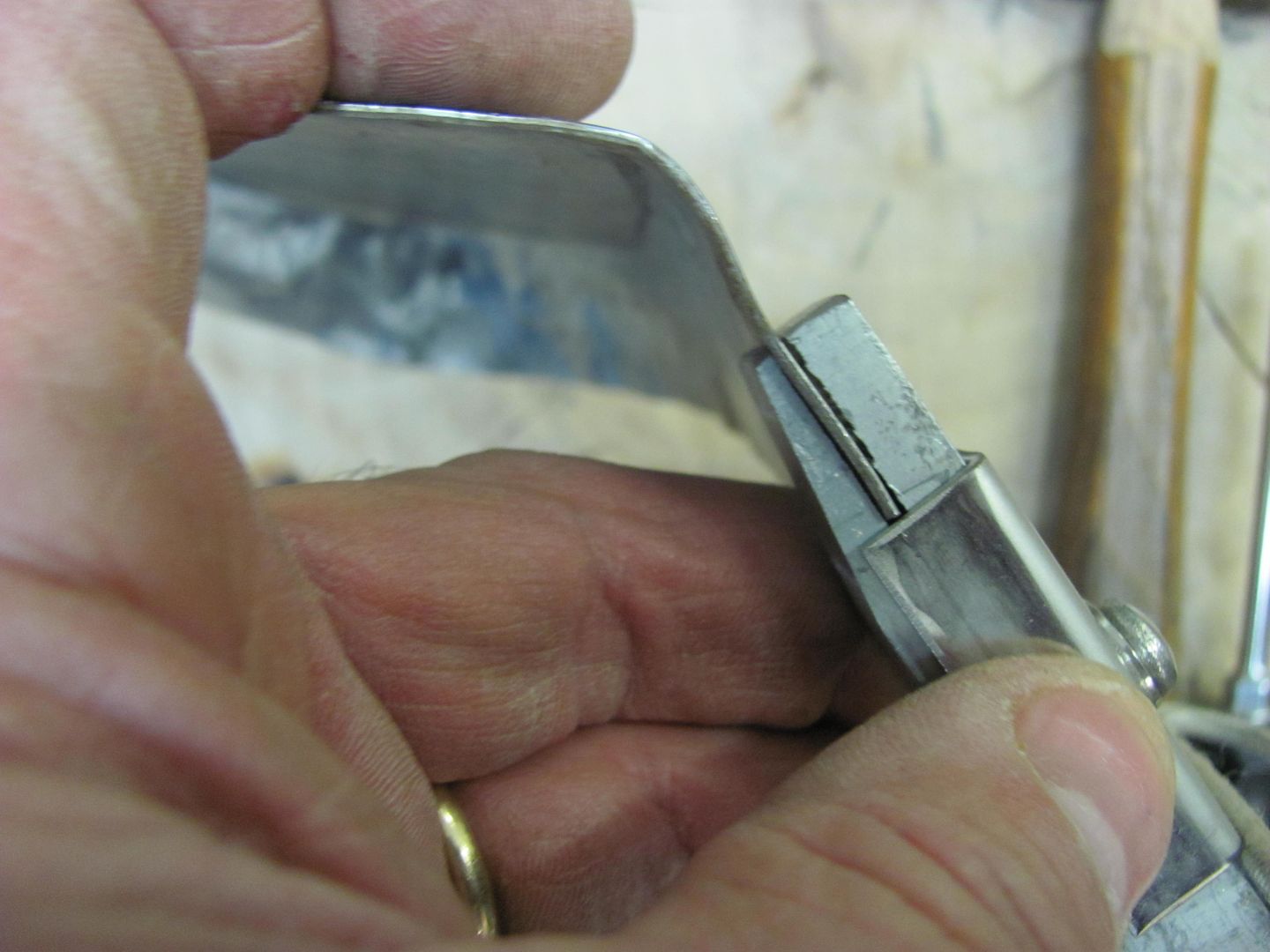
Use caution with moving fingers in close proximity of metal cutting devices, as I did draw a bit of blood (note pictures 4 and 5). Your results may vary, better or worse, so take appropriate precautions. (have band-aids handy or 911 pre-dialed, depending on how your luck runs)
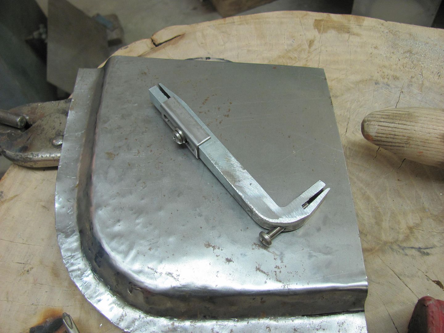
Short 10-32 screw and washer added to secure the stop at dimension desired.

Here's an "inner door" sample I whipped up real quickly, sorry for the lack of precision
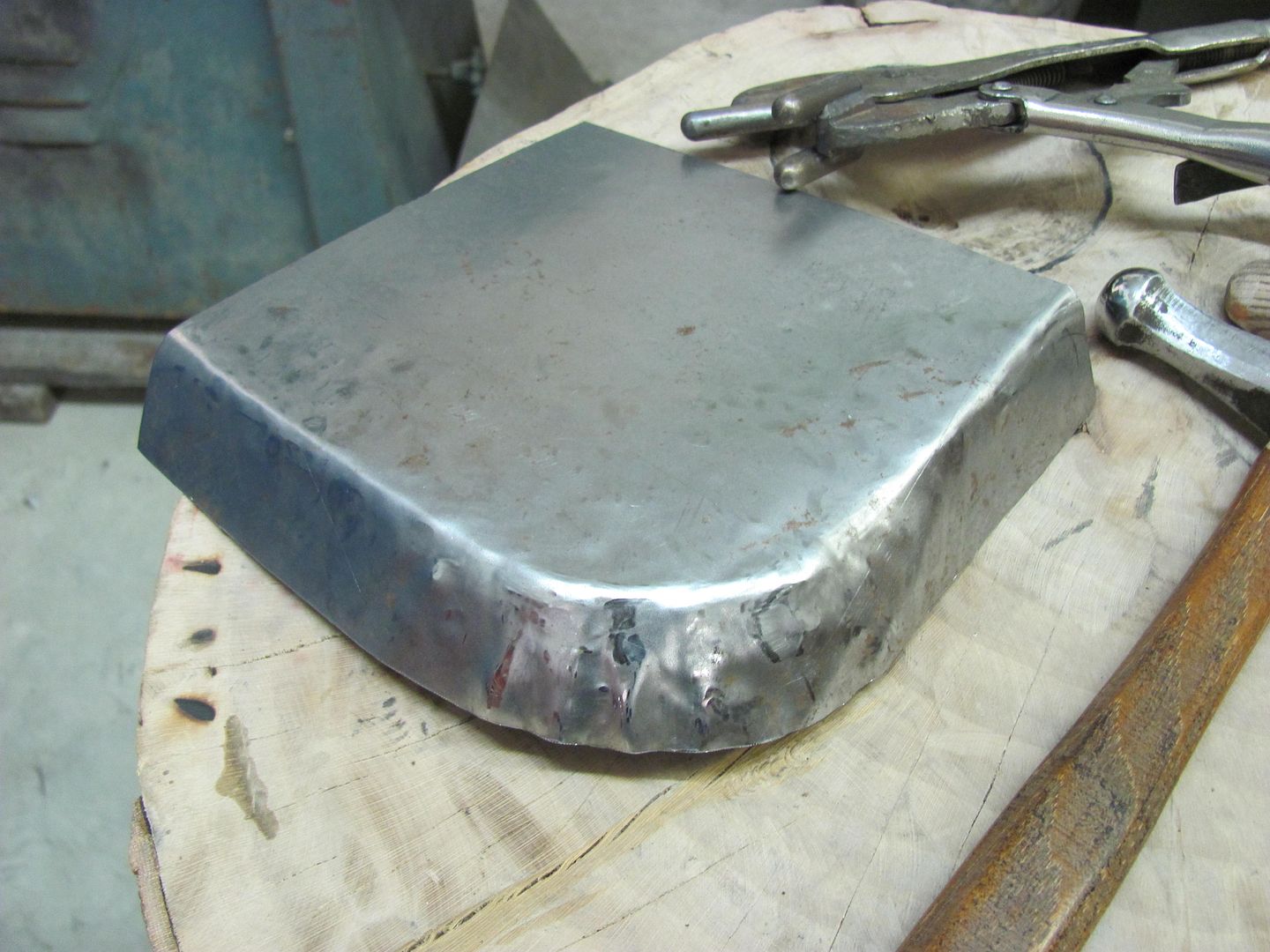
After panel and folded edge is cut to correct size for the application, mark desired flange width and adjust tool stops accordingly.
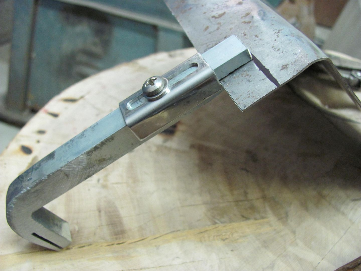
Bend slightly, working from one end to the other. Repeat repeatedly.
Two-ended tool allows you to use whichever end provides best leverage.
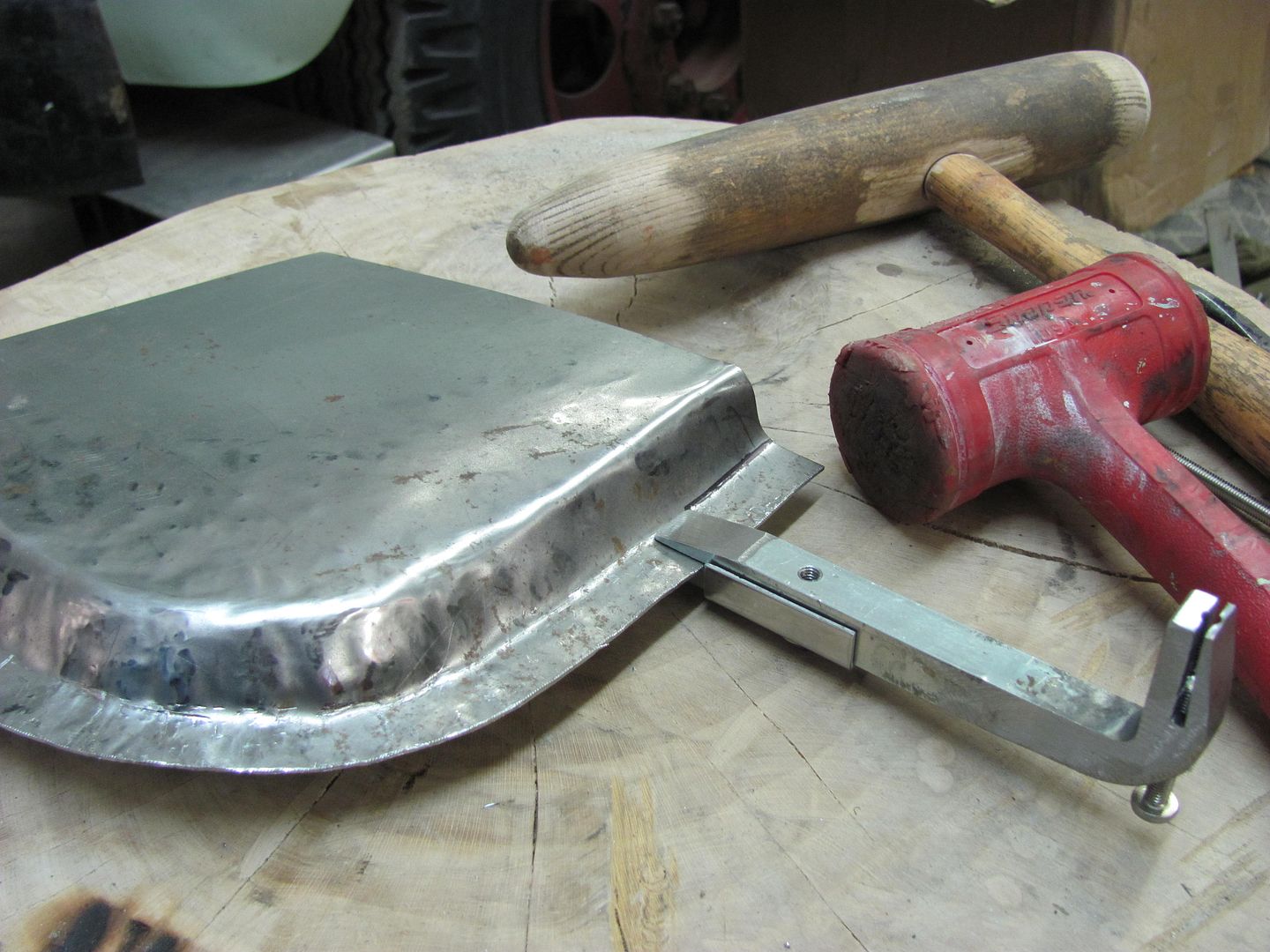
All ready for the "door skin" ............
 Last edited by MP&C; December 31, 2012, 06:21 PM.
Comment
-
the only real problem I see with being the floor mopper there is ... Maryland? sigh. Love the tool, thanks Robert!Flying south, with a flock of bird dogs.Comment
-
Thanks!
When I built my rotisserie, I used 1/4 wall square tubing (actually .22) which gives a slight clearance except for the welded seam down the inside. I had to make a tool to remove this weld for the various pieces to be able to telescope inside each other. My solution was to Tig a 1/4 diameter rod to the end of my cutoff wheel arbor. Got it right the first time, no wobble at all. Added a cheap 1/4" id bearing to the rod (not shown in picture) to be able to slide the bearing where needed, & apply pressure to the weld without the rotating rod burning your hand.
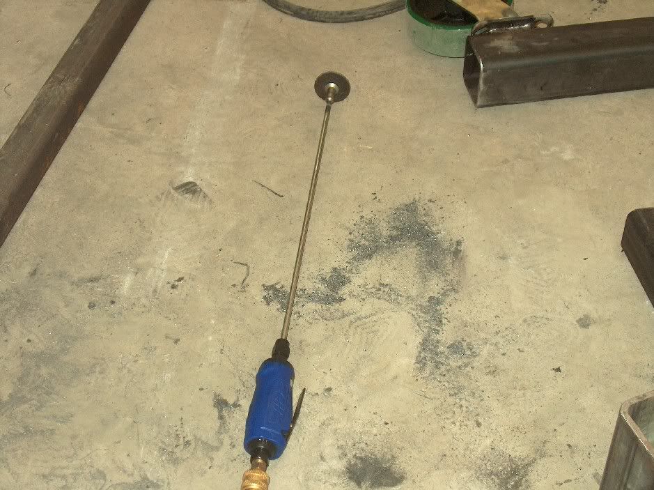
Works well for accessing those hard to reach areasComment
-
A couple years ago I helped with OJ's metalshaping demo in Berryville VA, where the focus was to be on hand tools so that anyone could duplicate the results inexpensively. I didn't get as many pictures of the event as I normally would with my typical tech threads done from my shop, (too many hammers in my hands) so this will be supplemented with some diagrams to make a good tech thread.
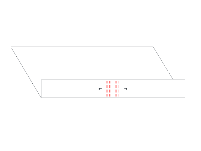
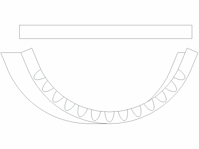
Your typical Lancaster type shrinker stretchers are in the neighborhood of 150+ and as we are trying to show these skills using "cheap" tools, this thread will discuss tuck shrinking. For the demo, I started with a 12" long panel with a 1-1/2" wide flange bent on the long edge. Then discussed some of the issues faced when shrinking a flange. For demonstration purposes, in the following pictorial we have a 12" long panel with a 1-1/2" wide flange.

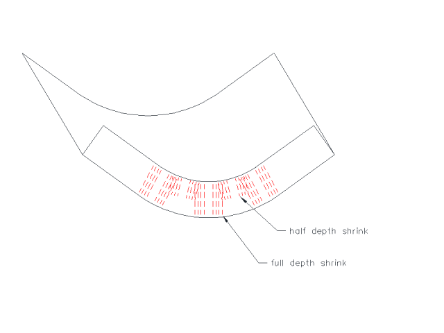
If we were to look at the same panel with a radius, formed by shrinking the flange, we would note dimensions similar to as follows:
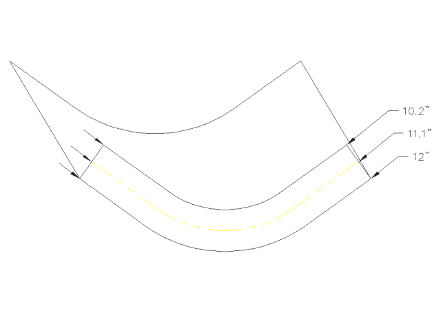
....where the 90 degree bend at the flange still retains its 12" length, the centerline of the flange in this case is shortened by almost an inch, and the outer edge of the flange shortened by almost another inch.
In working with the Lancaster/Eastwood style shrinker-stretcher machines, it is important to note that they are a linear device, the movement they introduce into the metal is in a straight line.
So that once a radius starts to form, and with the shrinking device still moving in a linear fashion, the outer edge of the flange will be put into tension as the centerline shrinks. Anyone who has used these devices will have seen this as the machine starts to lose its effectiveness.
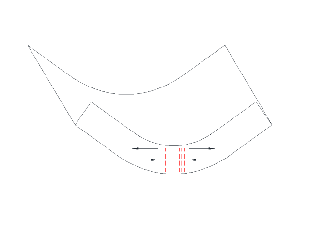
To counter this effect, we need to shrink the outer edge of the flange more than the inner. By simply alternating the depth of the shrink as shown, you can provide more shrink to the outer edge and the device will become more effective.
Another method of shrinking is with the use of tucks. Looking at their shape, the tuck has a wider "gather" at the edge of the flange as compared to the inside bend of the flange, so this eliminates some of the tension issues seen in the mechanical shrinker.
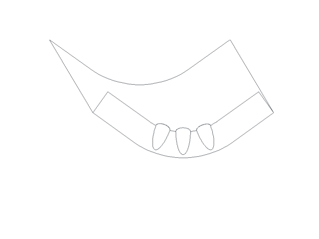
Where the demo was to concentrate on using only hand tools so that the participants could readily duplicate the results without the need for a major purchase, we did find the use of the Shrinker a good comparison, and by chance the tuck shrinking did prove to be faster and more effective for the wider flange we were using.
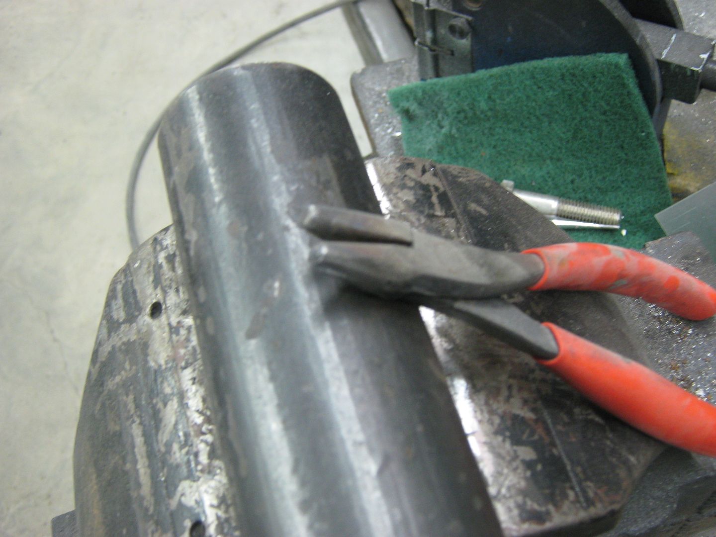
For the tuck shrinking, one can use tucking forks, rounded jaw pliers (by design or modification) or special designed devices. As an example, here is a set of tucking forks I made out of some scrap metal and 5/8 bolts turned down.
And a pair made from needle nose pliers..
Probably the biggest challenge with using either of the above tools is producing consistent tucks. To produce a flowing, consistent radius, we should start with consistent tucks, both in size and the spacing between them.
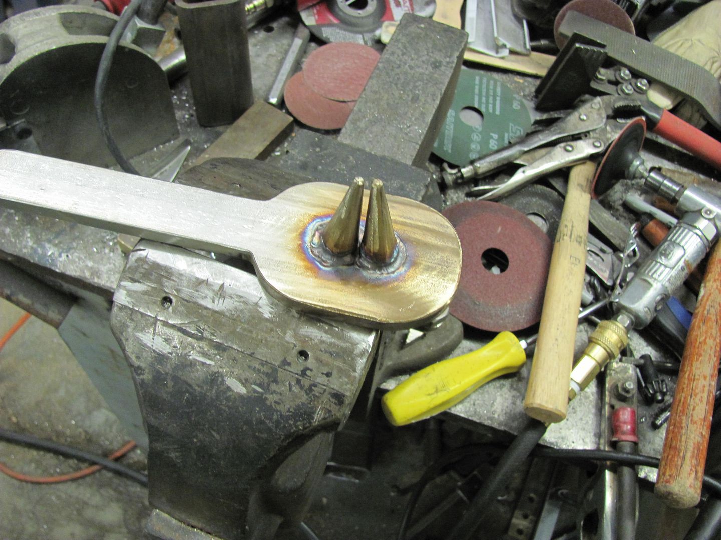
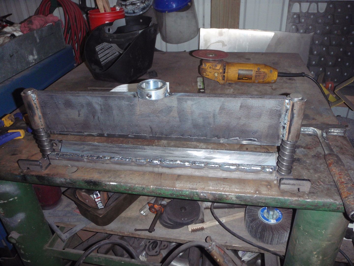
I decided to make a pair of tucking pliers out of Vice Grips, as the jaw adjustment on them would prove to give repeatable sized tucks.
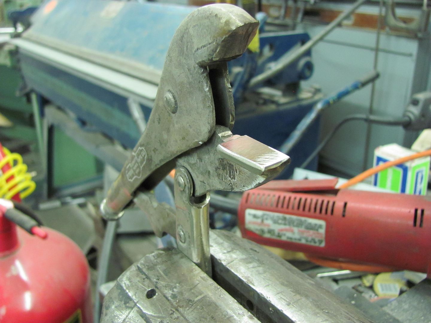
We'll start off by finding a pair of vise grips suitable for the job, which in this case means the jaw serrations are starting to wear and round off and won't grip much of anything else. Finish what has started by removing the serrations to produce a nice flat jaw on the bottom, and cut the top one off at about 30 degrees from its original position.
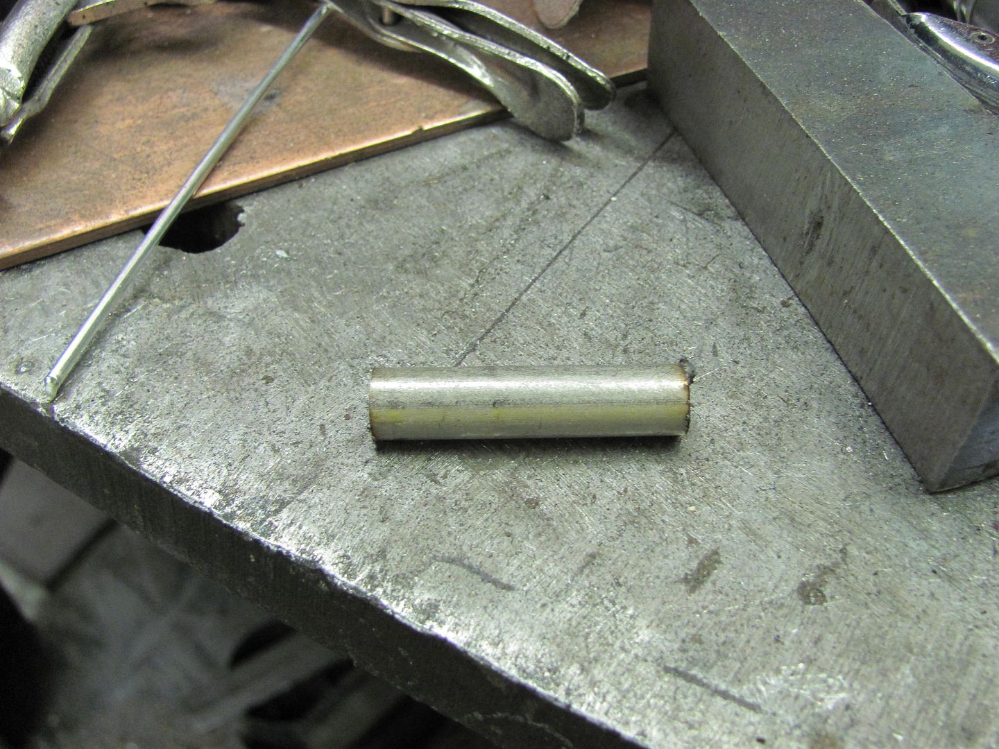
I had some extra long shouldered 3/8 bolts, perfect round stock for the job. Three of them were cut off to 1-1/2" length.
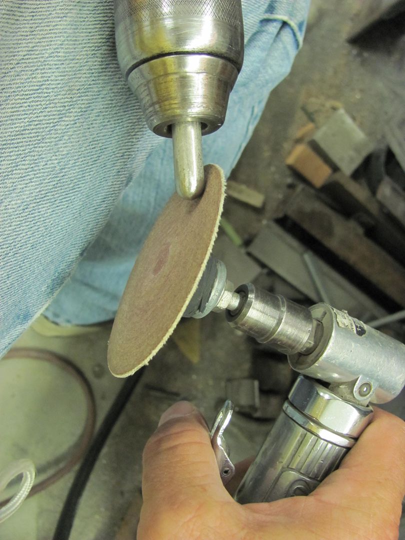
Here's my economy model lathe made by Dewalt...
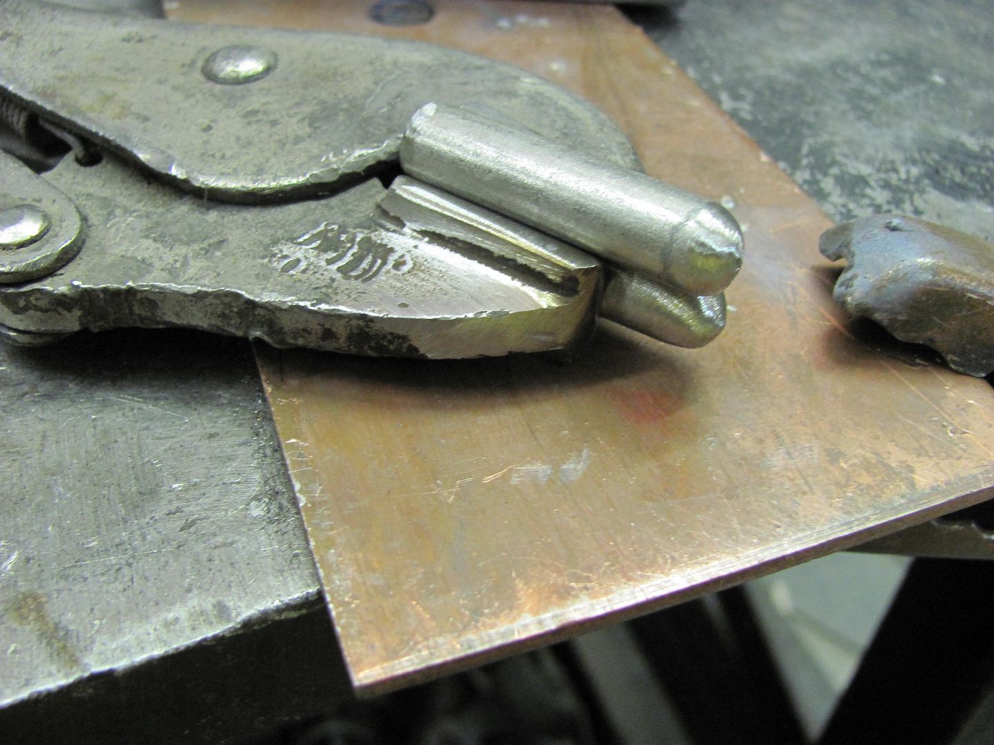
To set the spacing for the "fingers" the first is clamped in the vise grip jaw, centered.
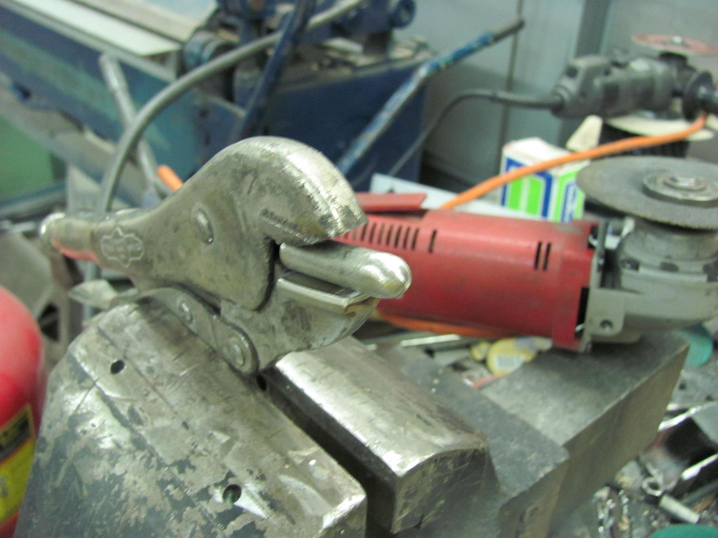
The outer is placed next to it and then welded down the outside, center finger removed, and then welded down inside. Here we should leave a slight gap of your sheet metal thickness to prevent any binding, which will allow a deeper tuck.
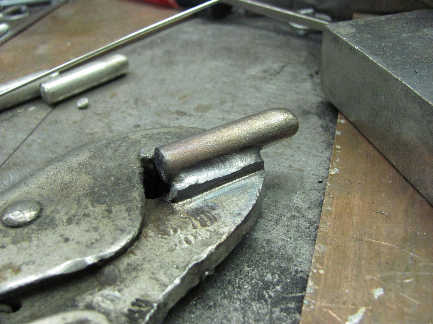
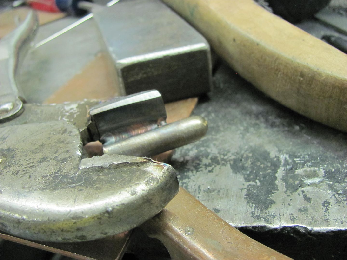
Repeat for opposite side, then weld center finger.
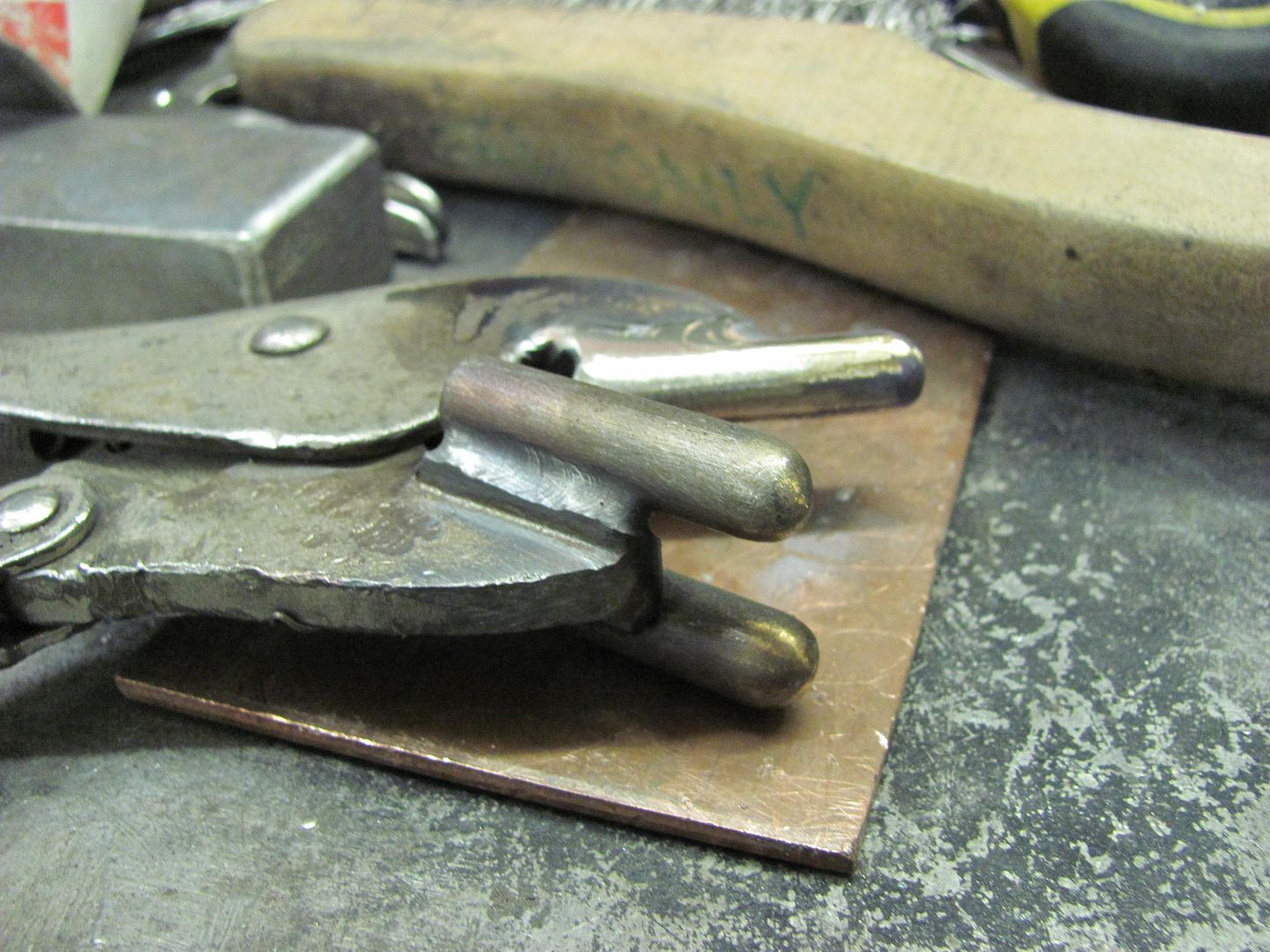
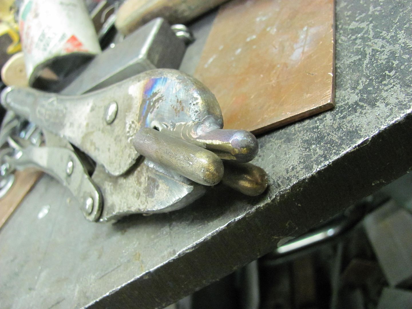
Note in the above picture the 30 degree cut of the upper jaw positions the center finger at an angle compared to the bottom fingers. It is this angle that will help to form the tuck's shape.
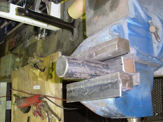
Of course I took my favorite anvil along to the meet, here clamped in the vise..
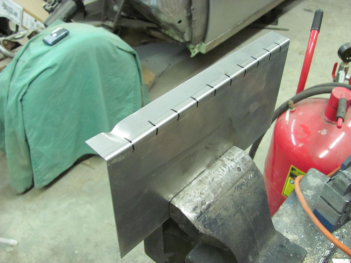
Again our object in this case is consistency, so equally spaced marks are placed on the flange, identical tucks made at each mark, and you can see the consistent radius along the panel.

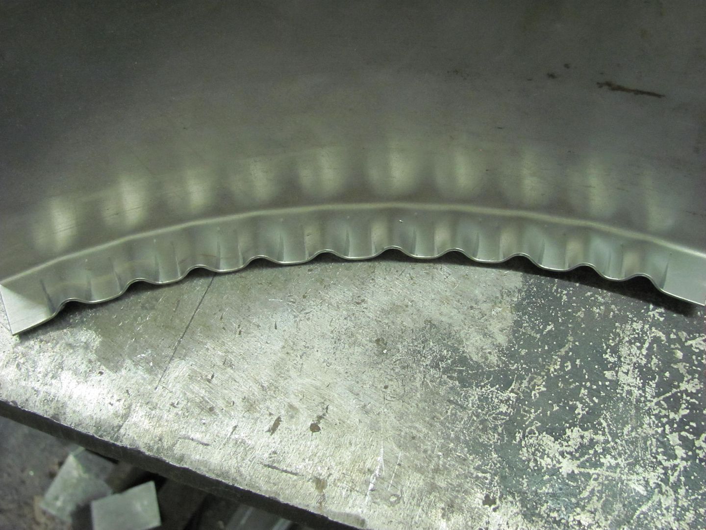
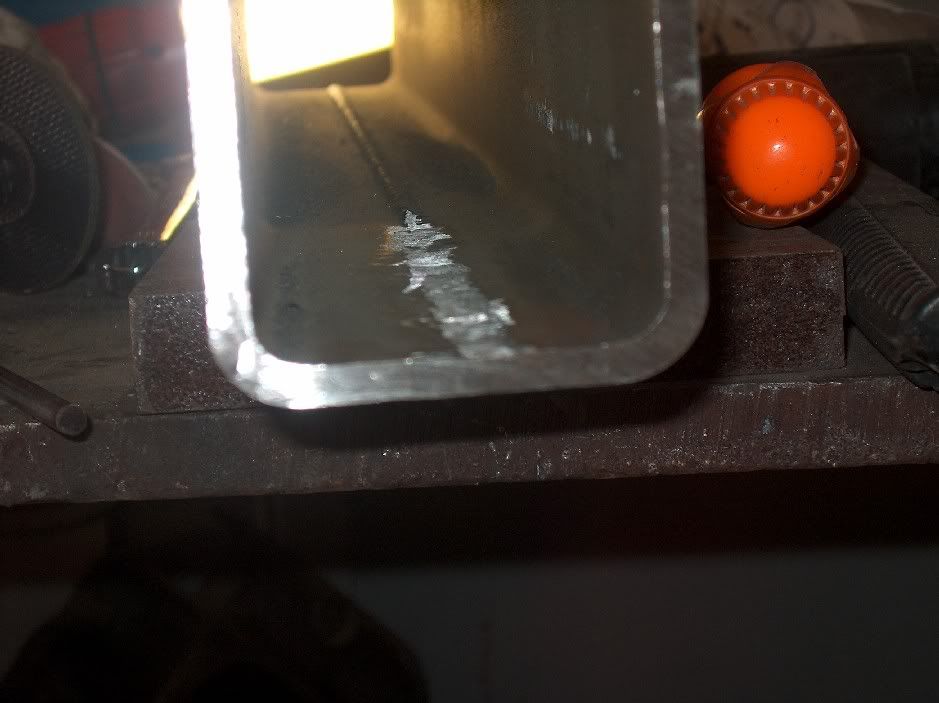
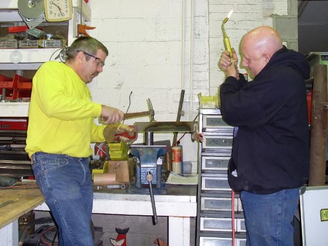
I use a O/A torch to heat the tucks prior to hammering them flat. Others prefer to not use heat, and can capture the tuck and flatten it very effectively without it. I am still working on this proficiency, so in the meantime, I use heat. We're looking for something like this, prior to hammering.
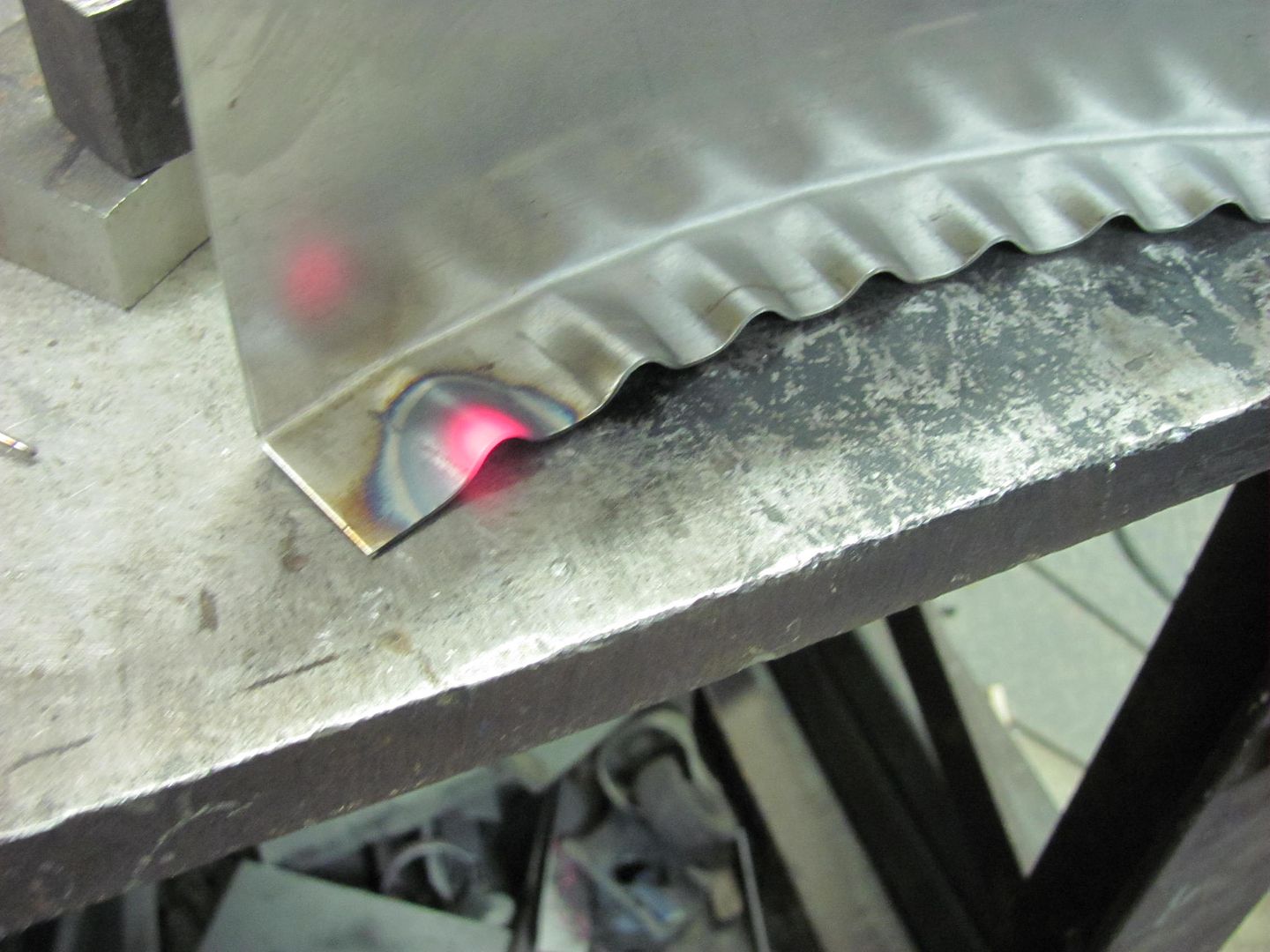
Here OJ assists with torch duties...
Another point to mention is that the hammering action tends to also spread the tuck back apart if not captured effectively. Where the picture above doesn't show it well, a good means of overcoming this would be to clamp a strap of metal across the ends of the newly formed radius prior to hammering, similar to this:
Then the hammering force will be more effective in flattening the tuck back into itself.

Comment
-
I am going to build a hydraulic press brake... until then, I paid $120 and bought this....
it works in your harbor freight hydraulic press
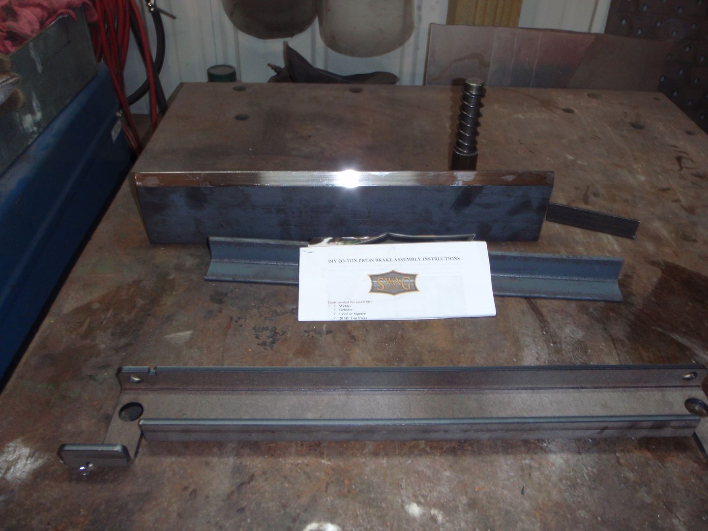
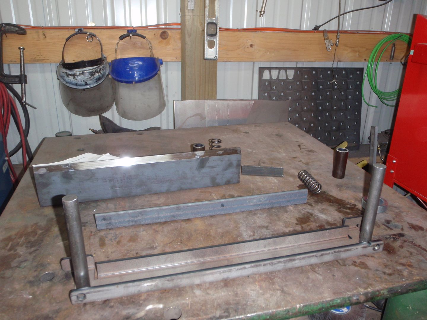
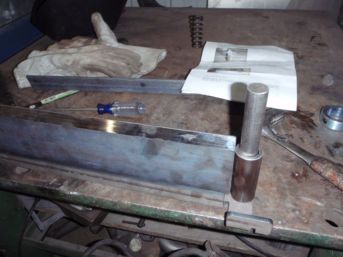
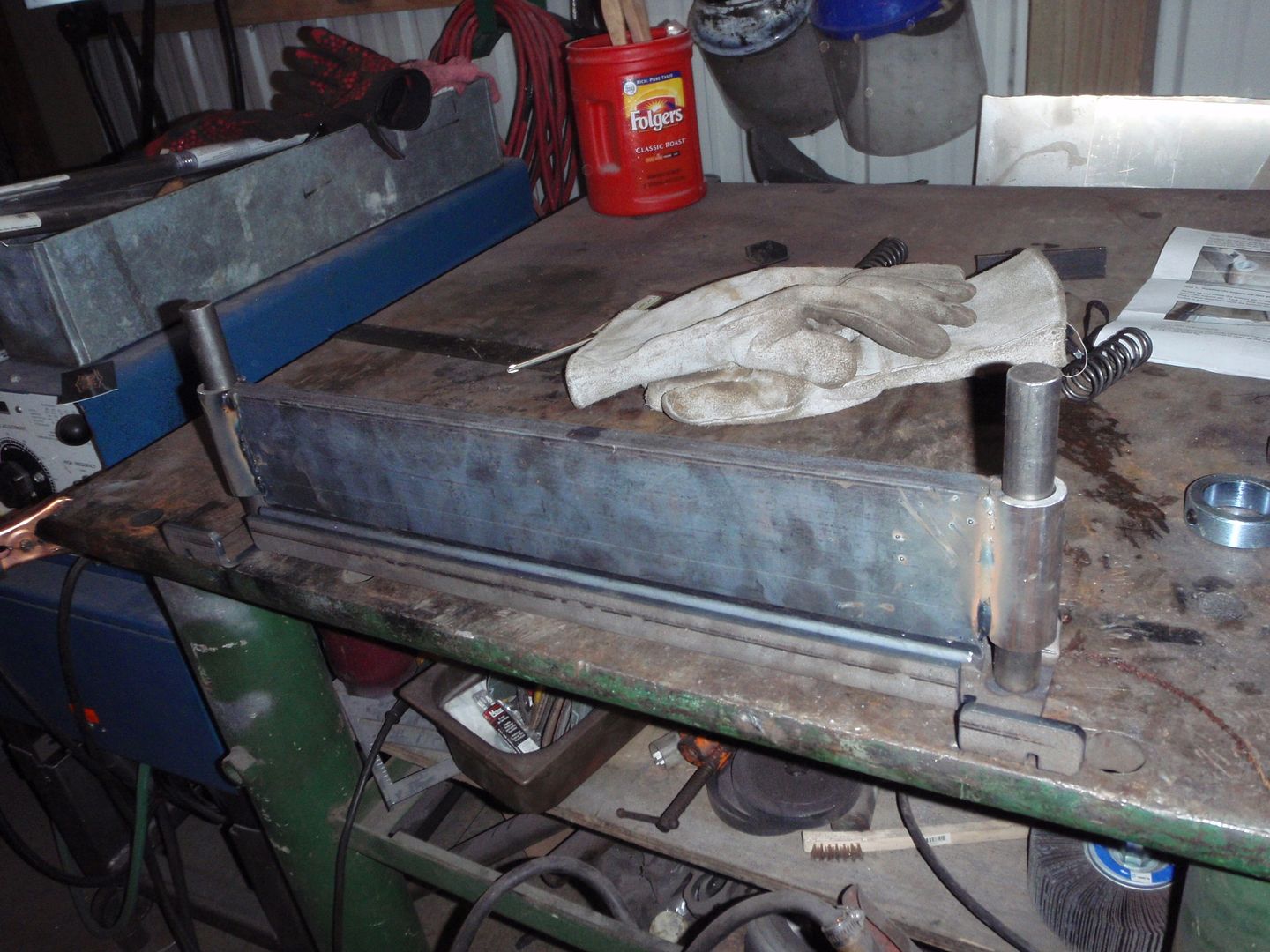
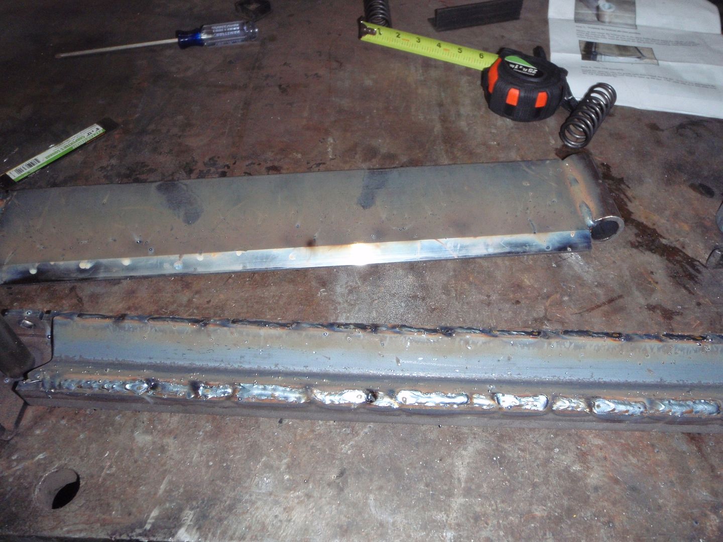
good for up to 5/16" steel bends. Which is more than enough, add this to my pan brake and I can do pretty much anything I need
I do suspect that it will do decreasing radius bends because the ends are unsupported (e.g. on a 90* bend, it will be 90* in the middle, at the ram, and 85*-89* on the ends), but as long as you center your piece in the press; it should turn out fineDoing it all wrong since 1966Comment
-
This seals it - given the combined talents of this forum - there's nothing that can't be done, nothing!There's always something new to learn.Comment
-
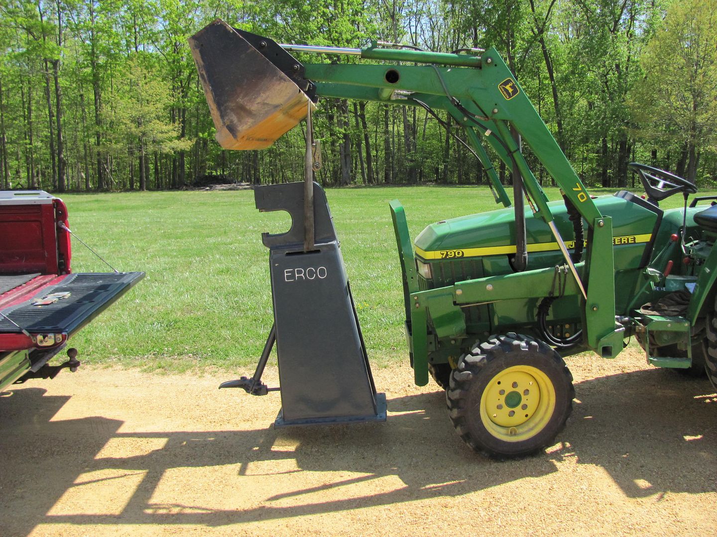
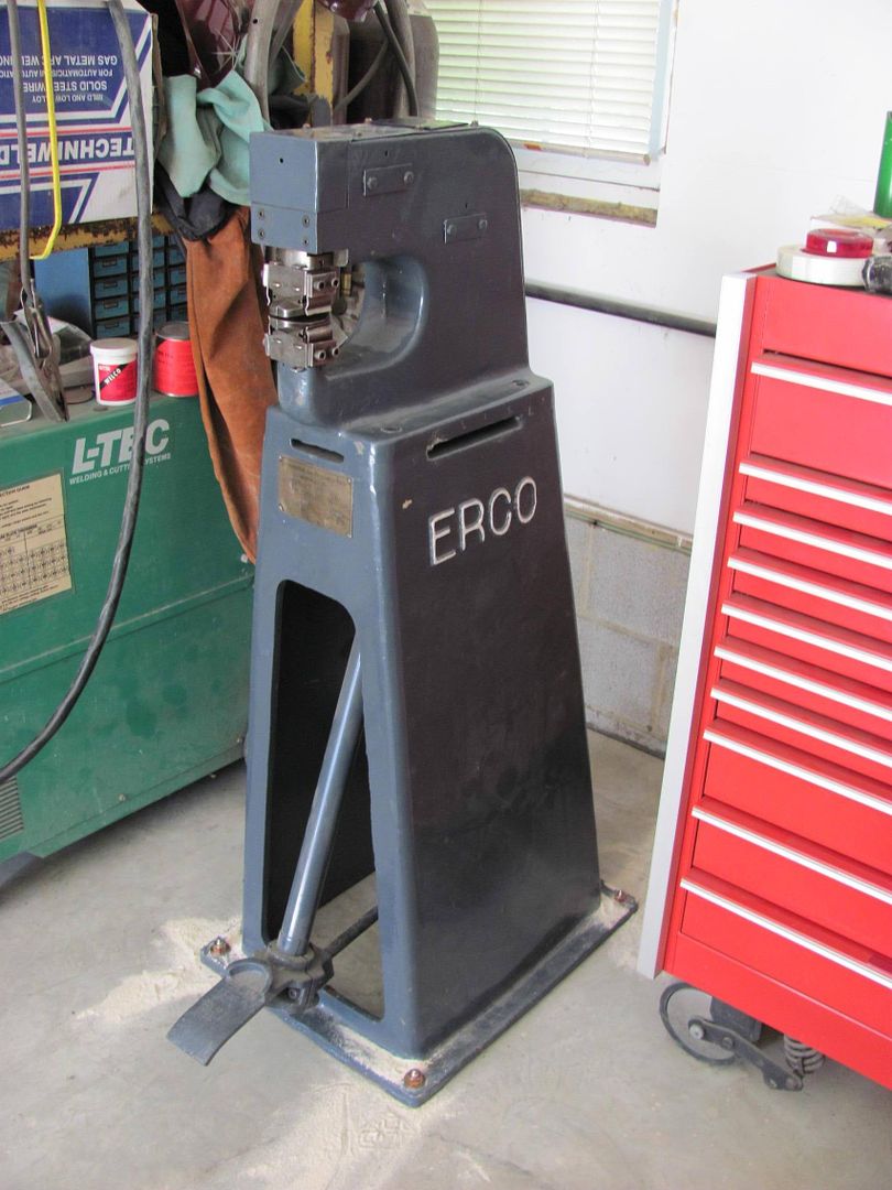
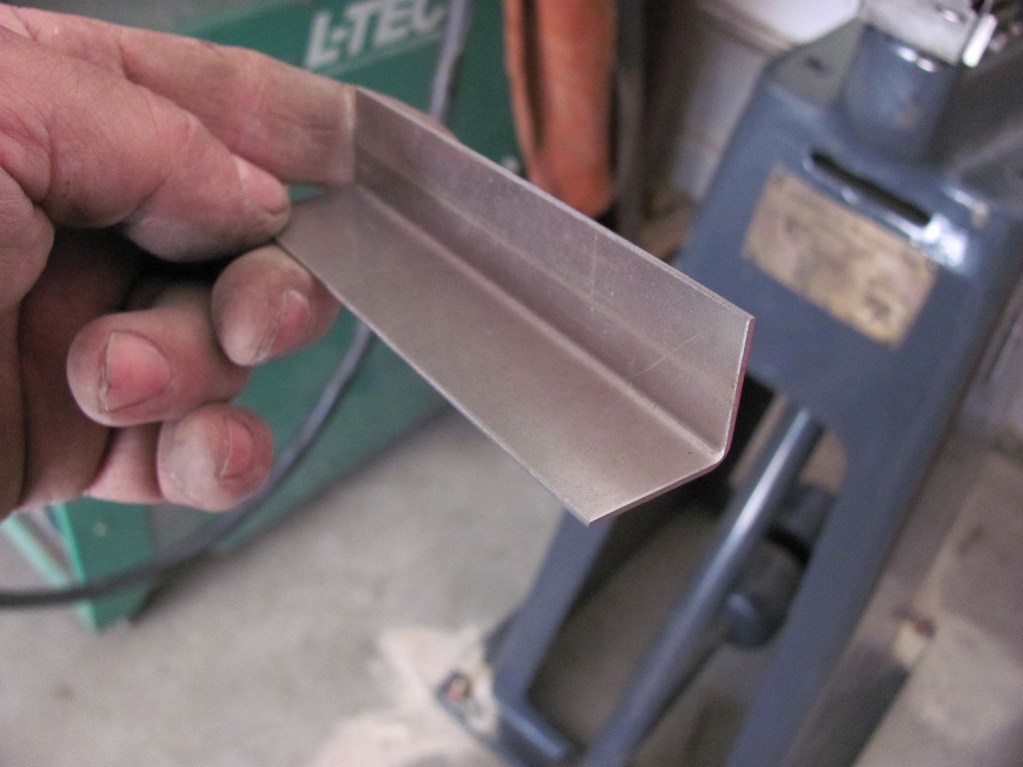
Made a trip to Long Island to pick up a "new" shrinker-stretcher for the shop, this originally came out of a Northrup Grumman aircraft plant on LI. Here's the unloading device ....
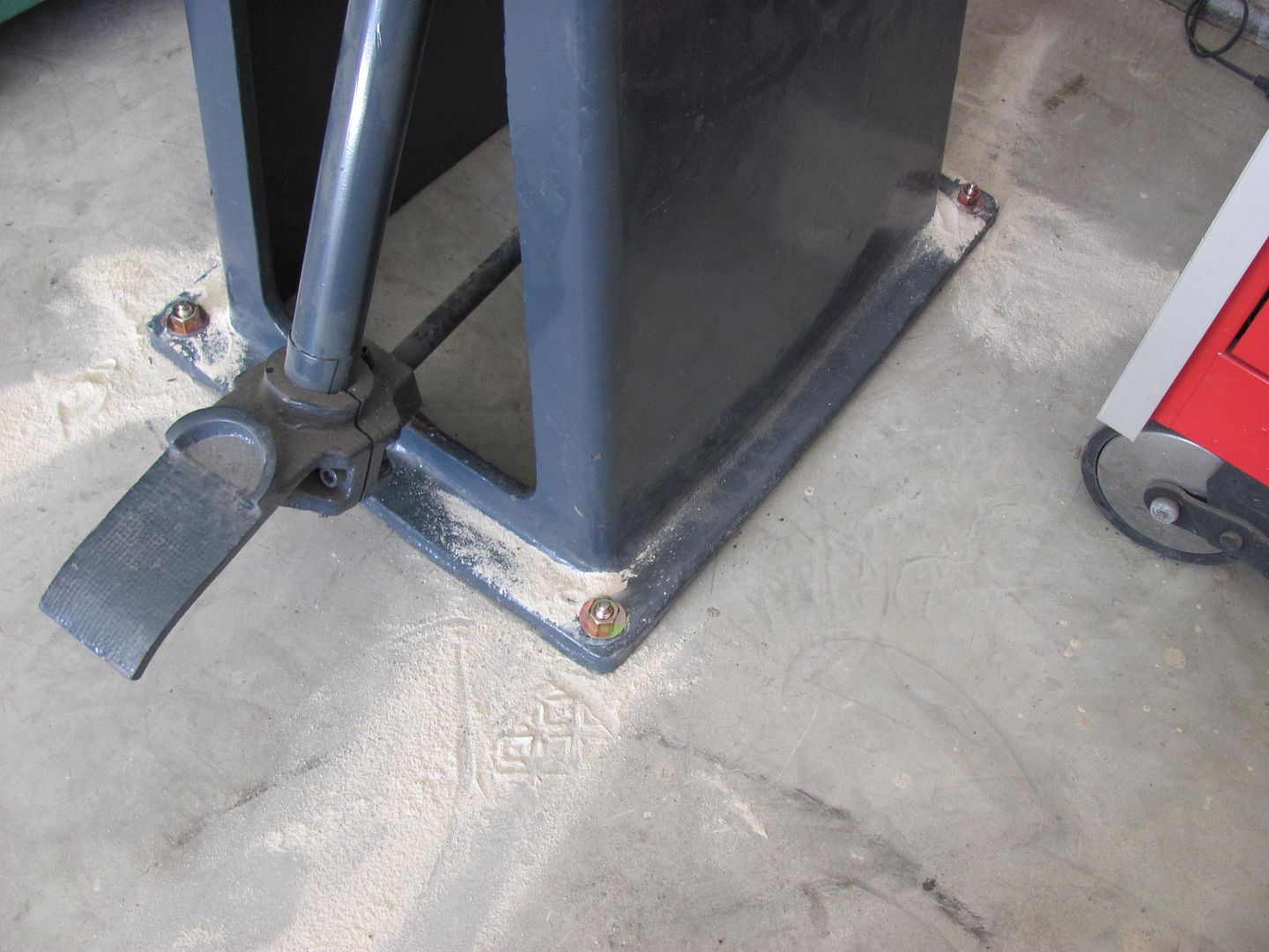
....and located in the shop, anchors installed to keep it from moving.
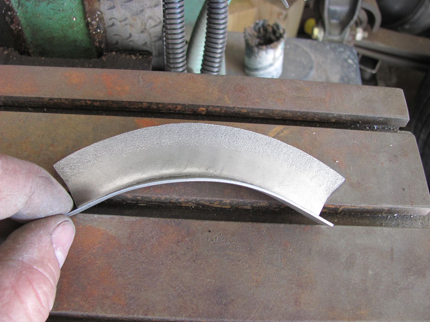
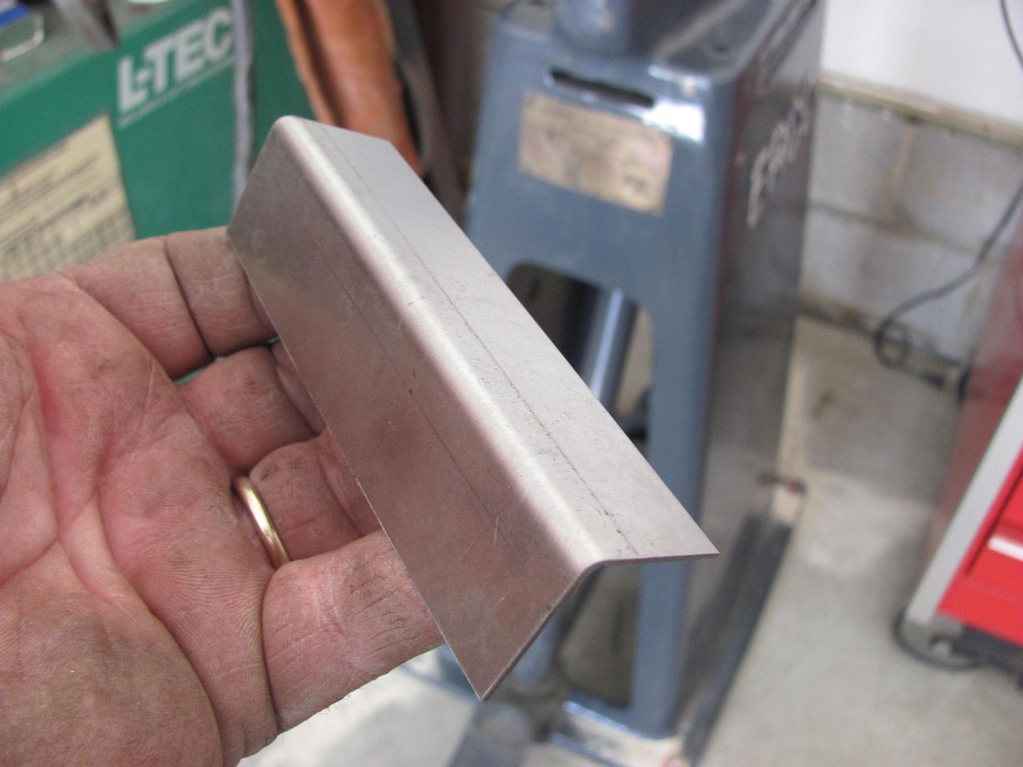
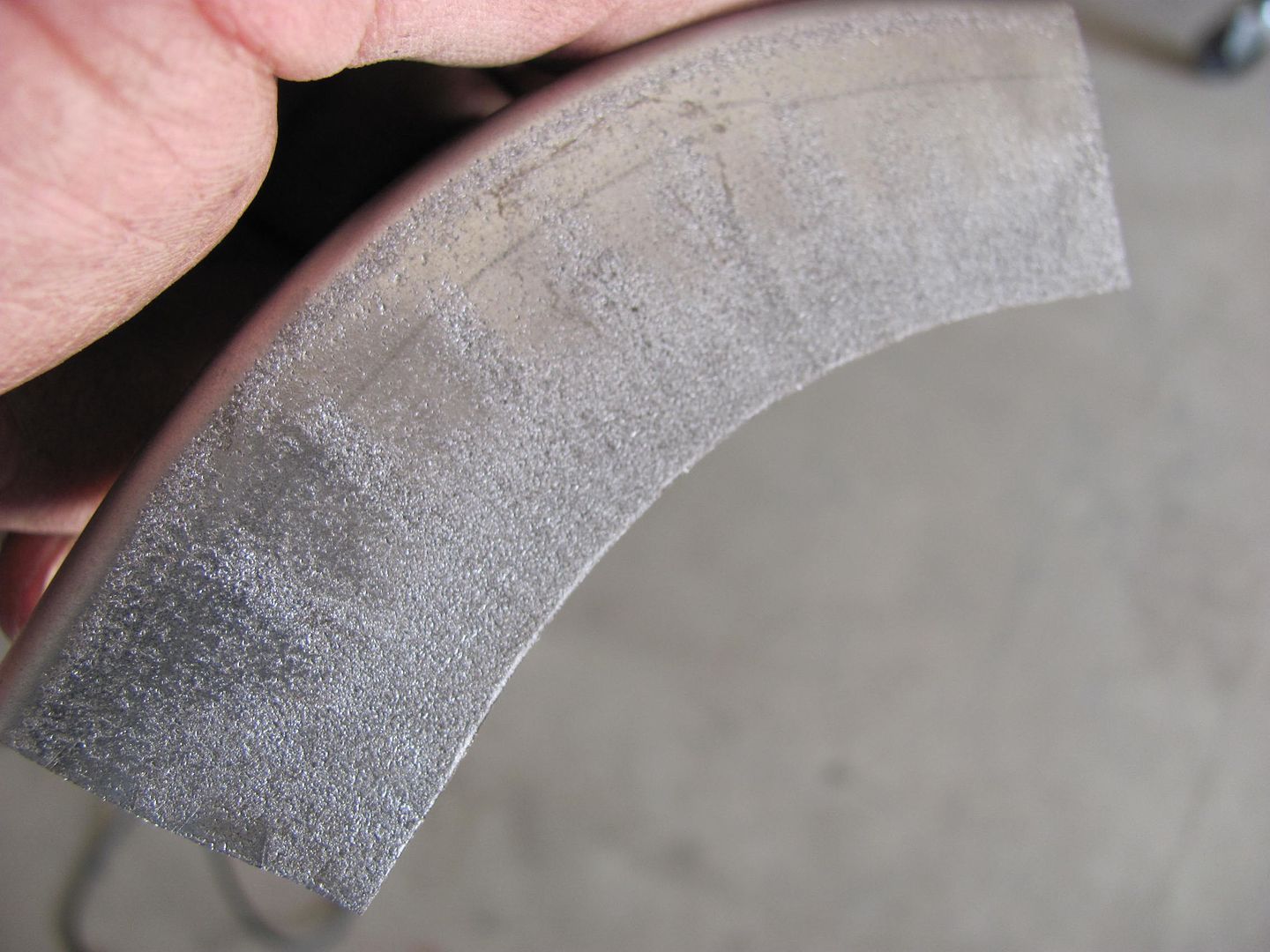
To show a couple test samples, we'll use about a 4" long piece with 1" flanges. The result shown is after about 4 passes, with a close up to show the "finish" result.
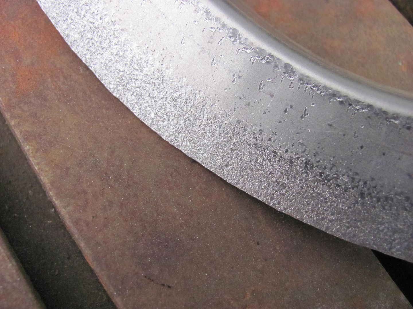
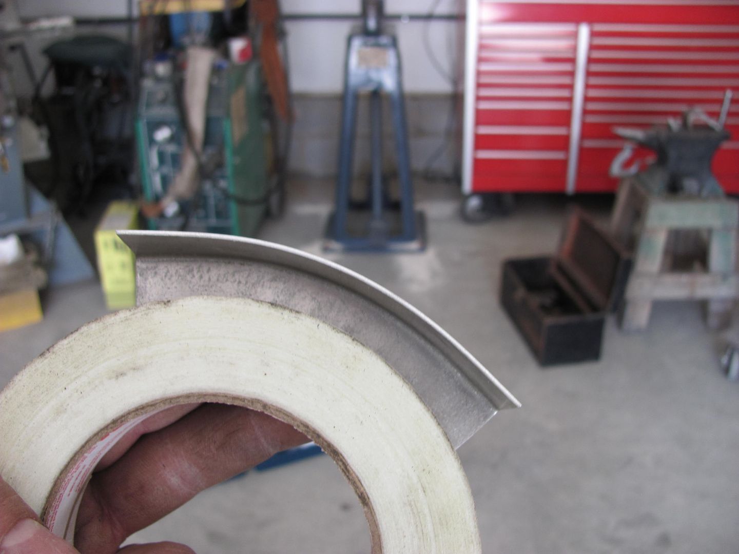
Shown against a roll of tape to compare the radius size we've accomplished..
Here's a closer shot to show the stippling on the shrinker jaw....
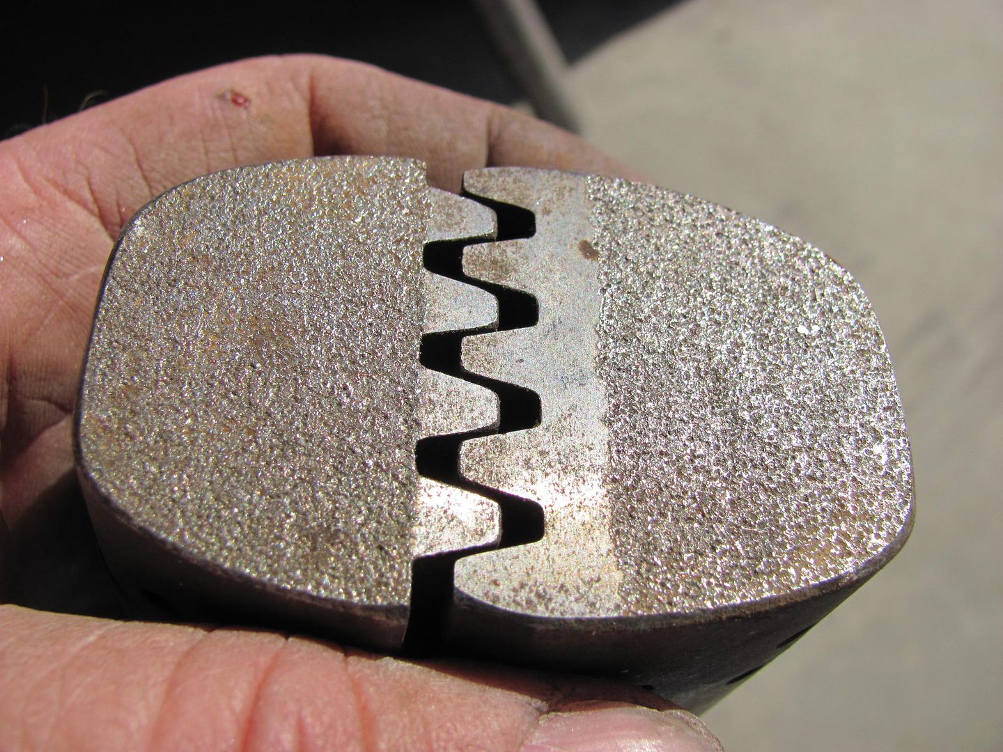
.....and the shrinking sample....
These Lancasters are what it will be replacing....
Comment
-
tools of the F14 TomcatComment
-
JWS4621 needed to press new bushings into a set of Fox body front lower control arms. If you've ever tried this, you know the stamped steel C shaped arms are very difficult to deal with and distort super easy.
First we built a C shaped spacer collar to slip in between the sides of the control arm when pressing. Then we realized the bed on my hydraulic press was far too deep to get the bushing centered under the ram.
I drug out some scrap steel, chopped it up and welded up an new bed with a 1" thick section of a Mopar 8-3/4" axle tube to serve as a lower support.
Literally took 5 minutes to press in the new bushings with excellent results.
While not as elegant as some of the tools shown in this thread, it does it's job quite well.
 Life is short. Be a do'er and not a shoulda done'er.
1969 Galaxie 500 https://bangshift.com/forum/forum/ba...ild-it-s-alive
1998 Mustang GT https://bangshift.com/forum/forum/ba...60-and-a-turbo
1983 Mustang GT 545/552/302/Turbo302/552 http://www.bangshift.com/forum/forum...485-bbr-s-83gt
1973 F-250 BBF Turbo Truck http://www.bangshift.com/forum/forum...uck-conversion
1986 Ford Ranger EFI 545/C6 https://bangshift.com/forum/forum/ba...tooth-and-nailComment
-
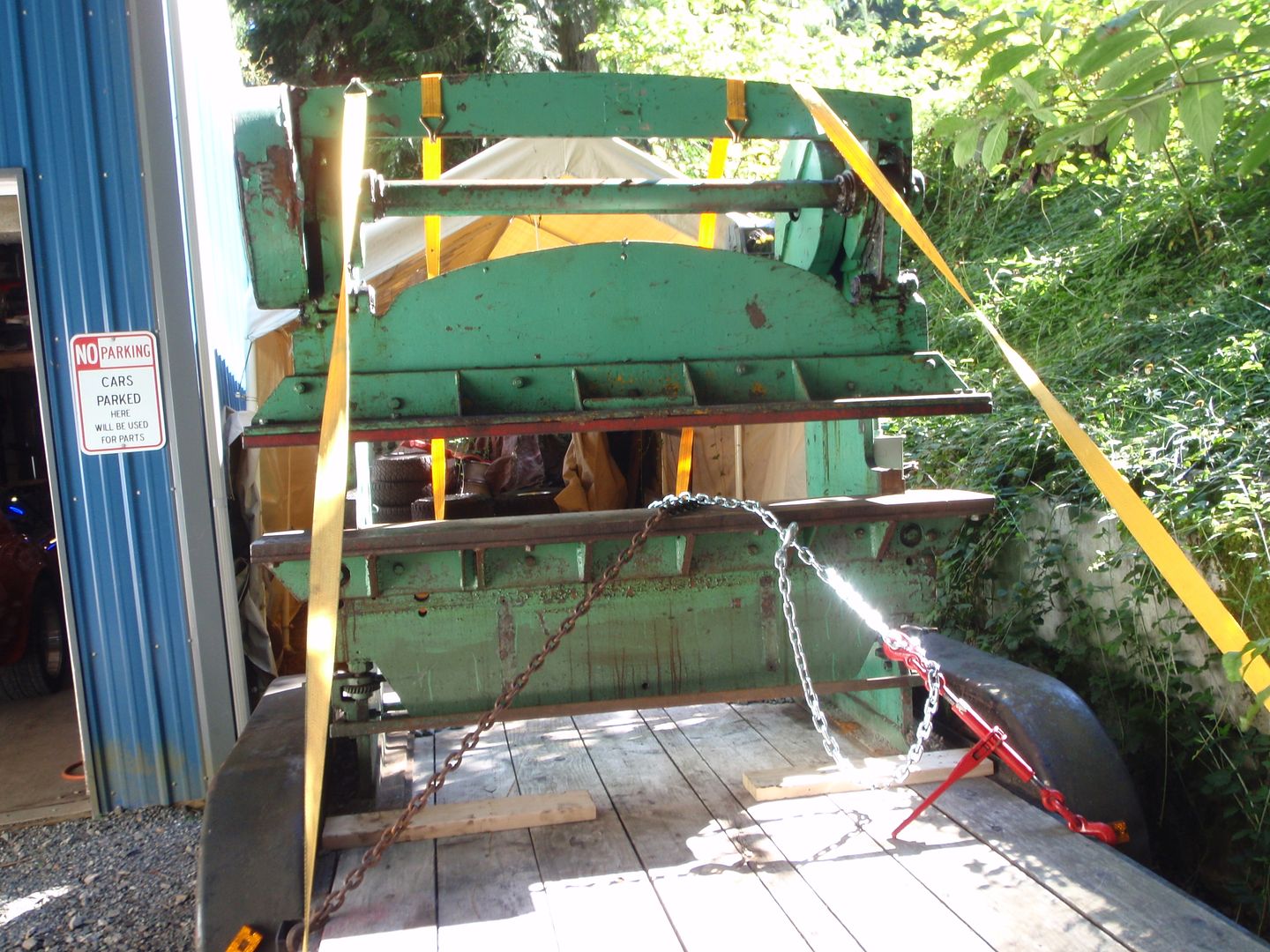
yeah, I know I posted about this in the general section; but figured the story belonged here
I don't know how the Canadians got ahold of this, but it's safely back on US soil
I used the winch to pull it off the trailer
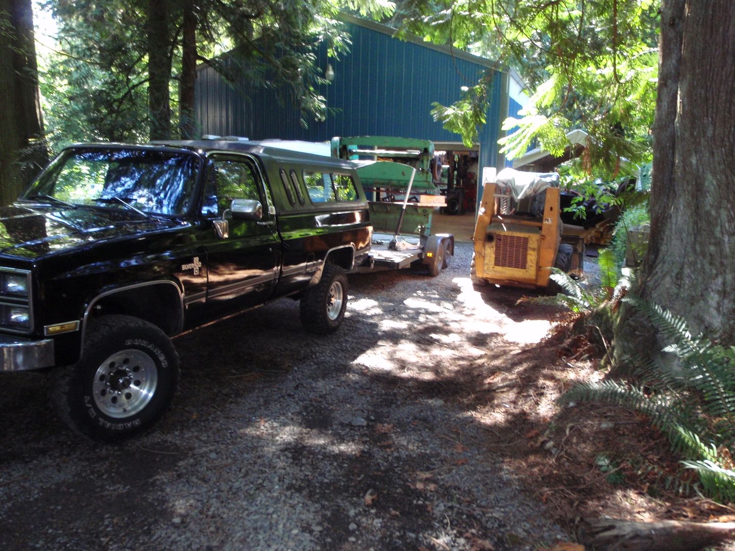
worked slick .... 12k winch didn't even flinch pulling it off
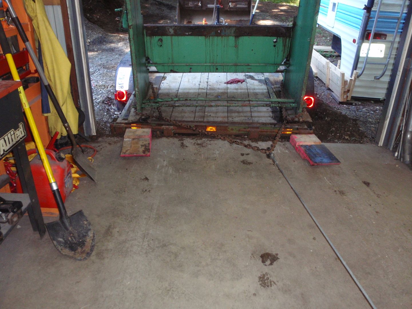
yep, I dug a hole in my driveway to slide it into the shop
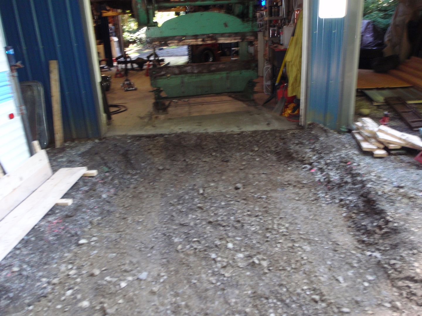
and it's almost home
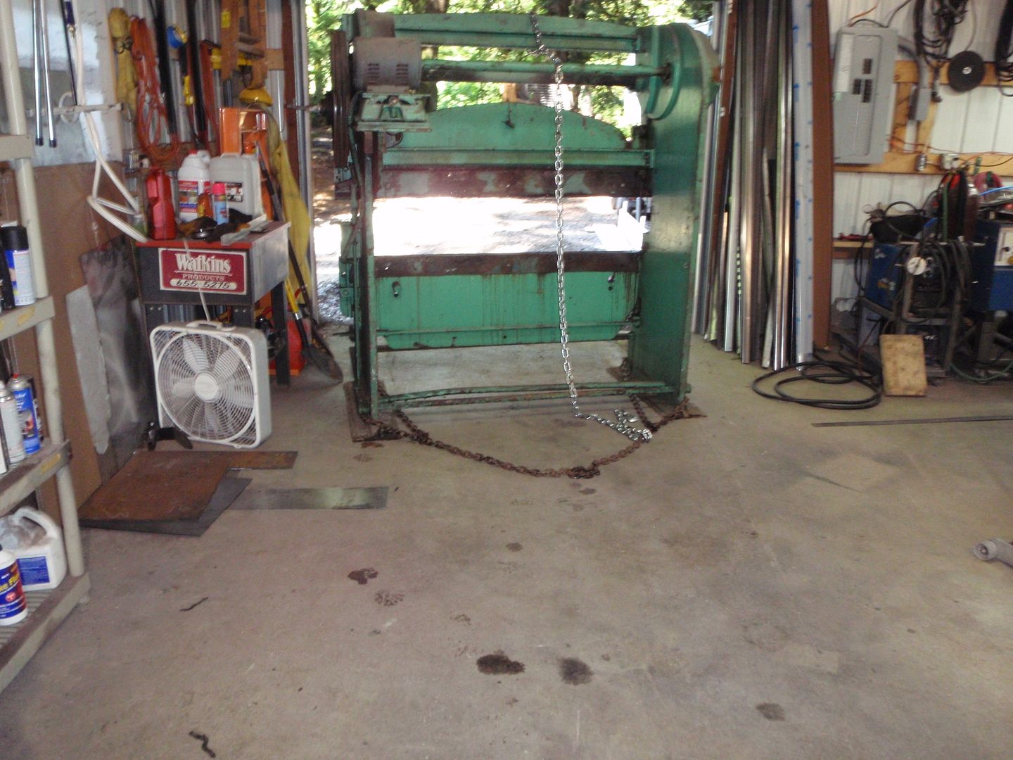
it's a 72" Chicago 30 ton press brake. I paid $700 for it and spent Friday going and getting it.... I have to replace the motor because it's a 3 phase motor - but a new one is on its way for $260.
I pulled the plates off to expose the bending bed.... no idea what I'm do with them, probably scrap them unless a light bulb goes off.
my dad owns a company that builds kitchen equipment for restaurants - so I've been using machines like this since I was pretty young - other best part, my dad said he'd help me out with some dies - that said, they aren't terribly expensive for used ones on ebay or craigslist...
now to build those floorboards for my SpiderDoing it all wrong since 1966Comment
-
Nice find, and a steal at that!Comment


Comment