Announcement

Collapse
No announcement yet.

mike343sharpstick's 69 Javelin project

Collapse
X
 
  • Filter
  • Time
  • Show
Clear All
new posts

  • The 70 and later AMC suspension is very similar in design to Ford's. My 66's suspension is pretty heavily modified, Don't waste your time on the coil over unless you're locating it to the LCA. Waste of time and money, just eye candy. What I will tell you what works, roller bearing spring perches. www.opentracker.com I believe sells them for AMC. This frees up a lot of binding. I believe you have struts too. I would get rid of the stock set up with the rubber bushings. Go with a rod end, This makes a huge improvement. It's so much more stable under braking and just plain works better. I have completely eliminated all rubber bushings and replaced them with rod ends. The lower control arm has a mono bearing. My Mustang steers and drives so nice. What's funny is everyone thinks with steel rod ends the ride would be harsh and noisy. it's just the opposite. It rides so smooth and soft. Despite going up in spring rate, the car rides softer now.

    My upper suspension


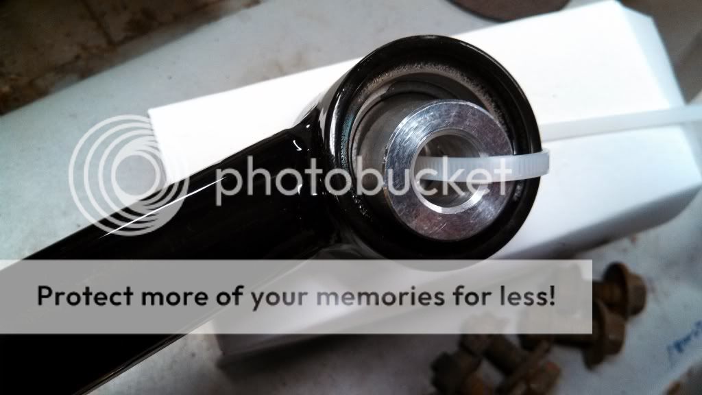
    I also installed a camber kit

    Tom
    Overdrive is overrated


    Comment


    • my suspension will be nearly exactly to what you have there!
      Biggest difference is my strut rods point to the rear of the car. Thanks for the heads up on the roller bearings.

      I didn't mention, the reason I'm making my own is that the only upgrade option is the control freak option, from what I hear it's a nice option but it replaces everything from crossmember to switching to a steering rack, and it's expensive.

      Thanks for the info on ride quality, that's what I've been curious about more than anything. Of course it will function better with rod ends, but I was unsure about certain road vibration hitting the chassis.
      Going from standard suspension to rod ends is one thing, going from upper trunions to an upper ball joint and rod end attachment points on the uca should be interesting if all go as well.
      Last edited by mike343sharpstick; February 18, 2016, 07:38 AM.

      Comment


      • I hear Control Freak customer service sucks big time FYI.

        Yeah, it's quite surprising at just how well it rides and drives getting rid of the rubber bushings. Even my idler arm has a bearing. Caster and camber is just about limited to my imagination with all of the adjustability of the suspension. About the only thing you will notice with all the rod ends, it feels like a set of low profile tires as far as ride goes. I have to be paying attention to notice it. You'd probably never know I had them if I didn't tell you. It's worth the time and money.
        Tom
        Overdrive is overrated


        Comment


        • So I have all the parts aside from the tubing.
          FK RSMX Rod ends (Same thing used by Magnum force for Mopar UCA's): $24 a piece from Summit and I'll need 2 per side.
          Weld-in threaded tube ends $13 a piece, also need 2 per side.
          QA1 Ball joint $46 a piece.
          Ball Joint Threaded Sleeve $31.

          Total hardware cost so far is $151 plus shipping just for one side!
          So for those of you buying control arms, you can see how much of that cost is in hardware alone.

          At this point I need to build the Jig. I'll be using a stock trunion/upper A-Arm assembly to duplicate the stock geometry at current ride height. Unfortunately I'm busy with my son for a cub scout event this weekend so I'm not sure when I'll next have the time to work on this. I think a vacation day away from my daily world of Engineering I.T. to do some metal fabrication might be in order soon. Working with my hands is good for my mental stability
          Last edited by mike343sharpstick; February 18, 2016, 11:51 AM.

          Comment


          • Upper ball joints look sweet, watch that the threaded sleeve doesn't get out of shape when welded (you can probably touch up small areas of the threads with those tiny Dremel cut-off wheels). What are you going to end up for caster with all this?
            ...

            Comment


            • My target for Caster is to be able to get 5 degrees or more if desired.
              As things are now, I have as much dialed in as I can get with the trunions, Not sure the number but it can't be more than 2 degrees. In stock form, caster is adjusted at the bottom from the strut rod, and If I lengthen that more, the tire will hit the front corner of the fender when turning.

              One of the advantages of the new upper control arm (In addition to no binding and squeaking in the trunion) will be the ability to bring the top/ball joint towards the rear of the car.

              When I build the A-Arms I'm going to build them at 4 degrees caster. I'll be able to adjust the caster, and camber by using the threaded rod ends at the mount point. Additionally have the ability to adjust caster by changing spacer thickness on either side of the A-arm rod ends. Basically I'll have the ability to move the entire A-Arm forward or back at least .5 and inch form center.

              In theory I should have the ability to adjust everything a bunch except the point where the upper control arms mount to the car, which is unfortunate.

              On the sleeve, I've read they are made a bit loose, so when heat is applied when welded they shrink a bit and are about perfect, we shall see! Spatter on the threads is never good however. Final welding will be Tig welds by qualified welder (e.g. NOT ME)

              Just ordered these! Thankfully I don't need to fabricate these too.
              Click image for larger version

Name:	NEW-SRE.jpeg
Views:	208
Size:	468.7 KB
ID:	1087136
              Attached Files
              Last edited by mike343sharpstick; February 18, 2016, 11:53 AM.

              Comment


              • Can you alter the upper control arm mounting location? If you can, you can gain a little bit of caster as well as raising the roll center. Raising the roll center is going to make the car corner a flatter and feel a little bit more stable. Beside Shelby doing this, Dick Guldstrand use to do this on his 1st gen Camaros and drive away from the other Camaro.

                I was going to ask if they made struts like that for AMC, sweet! I highly recommend this. Not only are you getting caster adjustment but those rubber biscuits on the factory struts compress inconsistently under braking. It changes caster. With my car when I still had front drums I could hit the brakes hard at 50 mph without my hands on the steering wheel and the car would stop dead straight. The new struts will do wonders. I would also check the lower control arm bushing. They take a lot of abuse following the arc of the strut. Mono bearing! Keep in mind you may run into some bump steer issues as you start to move stuff around. Oh yeah, almost forgot about this too. See if you can do away with the rubber bushing in the idler arm and replace that with a bearing too. It mtakes a modest improvement in parking ease but it adds a nice precise feel to the steering.

                Since you're doing this upgrade, one thing I would highly suggest, learning from my adventures, invest in a caster/camber gauge and do your own alignment!
                Tom
                Overdrive is overrated


                Comment


                • Good question, I've read all about the Shelby, and Guldstrand mods.
                  But nope, not an option. Those options also improve anti dive as well I believe.

                  I am slightly changing the roll center by using longer studs on the upper ball joint. That's what's cool about the QA1 pieces, you can change out, or purchase different stud lengths for all the ball joints. I bought basically the medium length versions as a starting point.
                  Going to measure the stock and updated geometry when I build the jig, I may even model it in 3D so I can determine roll center other info down the road. Pun intended 😄

                  Comment


                  • Mike

                    I have an 68 AMX rolling shell that I am thinking building a Rallycross car with. I am also looking at making a trunnion replacement for the car. Here is my basic plan.

                    Lower control arm and upright will be a 70+ version.
                    Upper control arm I am going to fab up and use stuff from these guys. http://spcalignment.com/race

                    For shocks I am going to go with a similar 70+ setup but weld in a lower coil over shock mount like this. https://www.aa-mfg.com/coil-over-mount-with-1-2-hole
                    Then Ill either cut open the shock tower to make a similar mount up top or weld another one up in the shock shock tower if I dont cut it open.

                    I have already had some stuff made like the lowering plates, caliper brackets, and new spindles for the stock upright. So I am hoping all I have to do is work out a proper upper control arm.

                    Once the car is in the shop and I get it torn down Ill be able to get going on it.


                    Comment


                    • GT, that's a great plan, I can't wait to see how that comes together!

                      Well, I finally got the jig together, turned out OK, a bit of a snag to fix but no big deal.
                      Good thing I ordered the longer ball joint. At current ride height, the upper control arm will be at about 4 degrees with the 70 suspension upright.
                      My Stock upper a-arm with '69 Trunion suspension the upper control arm is at about 2 degrees at the current ride height.

                      Here is something odd, my car is about an inch and a half lower than stock, so a stock pre-70 front suspension would have the opposite of camber gain for the first few degrees of front suspension travel. That can't be good?
                      Last edited by mike343sharpstick; March 7, 2016, 09:27 AM.

                      Comment


                      • Click image for larger version

Name:	image_44992.jpeg
Views:	230
Size:	1.34 MB
ID:	1090776 Here is the jig holding the trunion in the identical position it is in the car.
                        Last edited by mike343sharpstick; March 9, 2016, 10:24 PM.

                        Comment


                        • Click image for larger version

Name:	image_44993.jpeg
Views:	227
Size:	1.78 MB
ID:	1090779 Here is the 1970 upright in the jig, and now it's basically connect the dots!
                          Last edited by mike343sharpstick; March 9, 2016, 10:25 PM.

                          Comment


                          • I like your process on this! It'll be interesting........

                            Dan

                            Comment


                            • I like how you made the jig..

                              Comment


                              • If you're going to adjust caster via the rod ends, make sure you make one of the sides of the UCA with a turnbuckle or something so you don't put side excessive side loads on the rod ends. Boy are you going to like the rod ends! Don't forget the LCA either.
                                Tom
                                Overdrive is overrated


                                Comment

                                Working...
                                X