


(Words and photos by Dave Matyjasik) – (Editor’s note – Yesterday we started what will be a multi-part series on the dissection and reassembly of a C7 Corvette that was blown up on a chassis dyno after receiving a supercharger and a “custom tune” from a shop that had little experience with the direct injected LT series of engines that power these mighty cars. Yesterday’s story documented what it took to get the engine out of the car and today we get a look-see inside the mill to gander at exactly what happened when the dyno rollers were being spun by the (formerly) boosted engine. Like we did yesterday, all the words and photos you’ll see from here on out come from Dave Matty unless specified by us.)
Onto part #2!
We dropped the motor off at Steve Ashworth Racing Engines in Fuquay, NC and started to help with the inspection and tear down. These are all the photos. Most everything looks like LS base on the bottom. I haven’t torn into a variable cam timing motor so that may be straightforward as well as the DOD setup that’s been in trucks for a while.
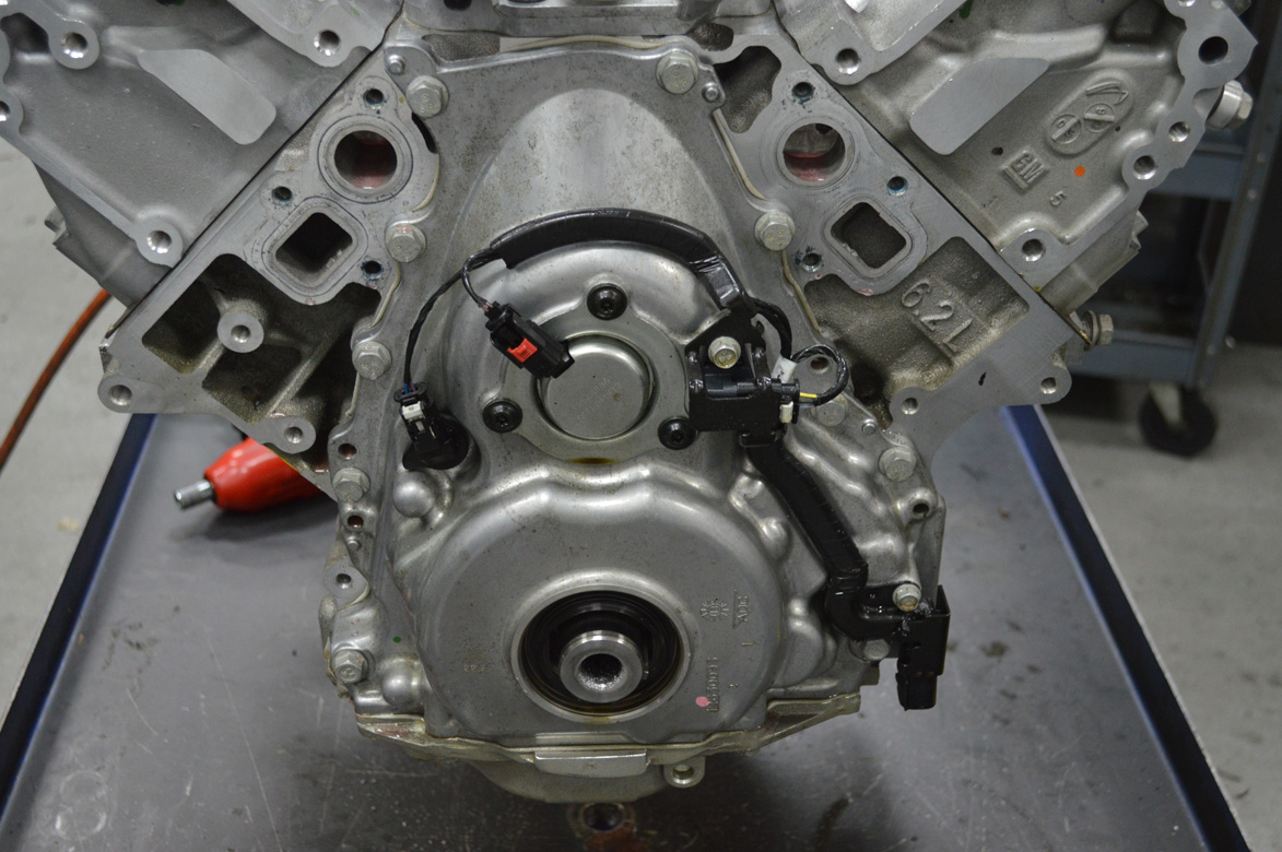
Here’s the timing cover with variable cam adjuster and sensors.
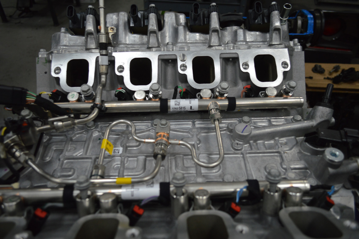
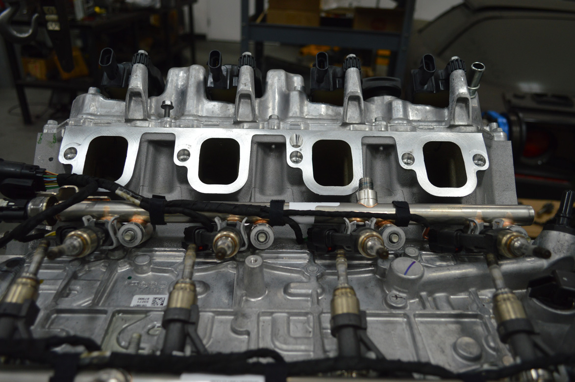
Fuel rails and injectors.

Closeup of mechanical fuel pump.
Fuel injectors removed. Covered in aluminum piston powder, more of that below.

The ends of the injector are not supposed to look like that.
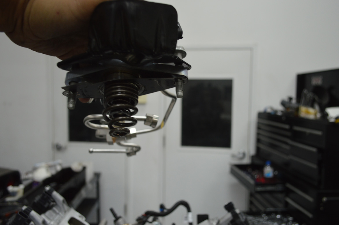
Mechanical pump and spring, fairly simple design of course with more electronics.
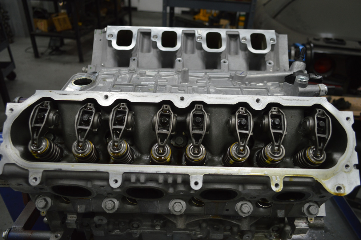
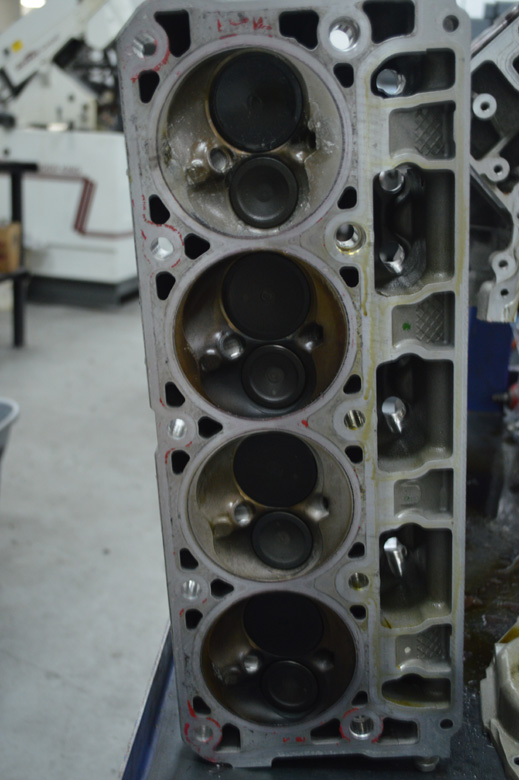
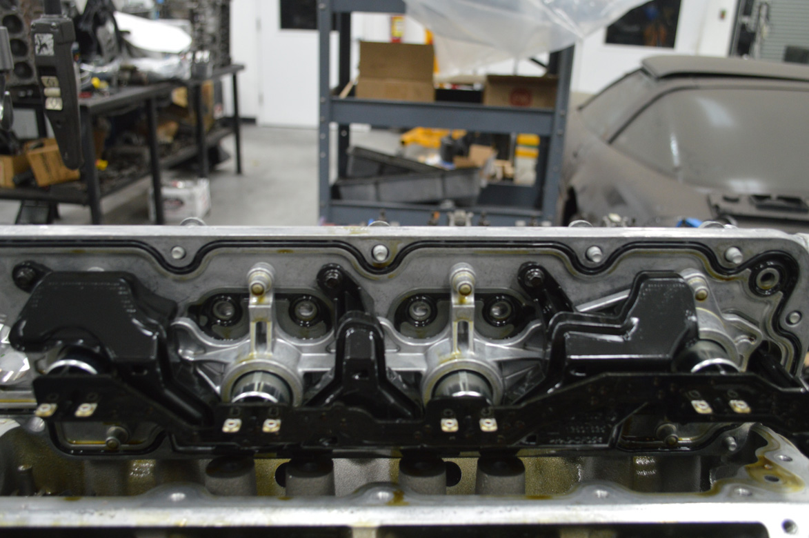
Under valve covers looks like normal LSx engine.
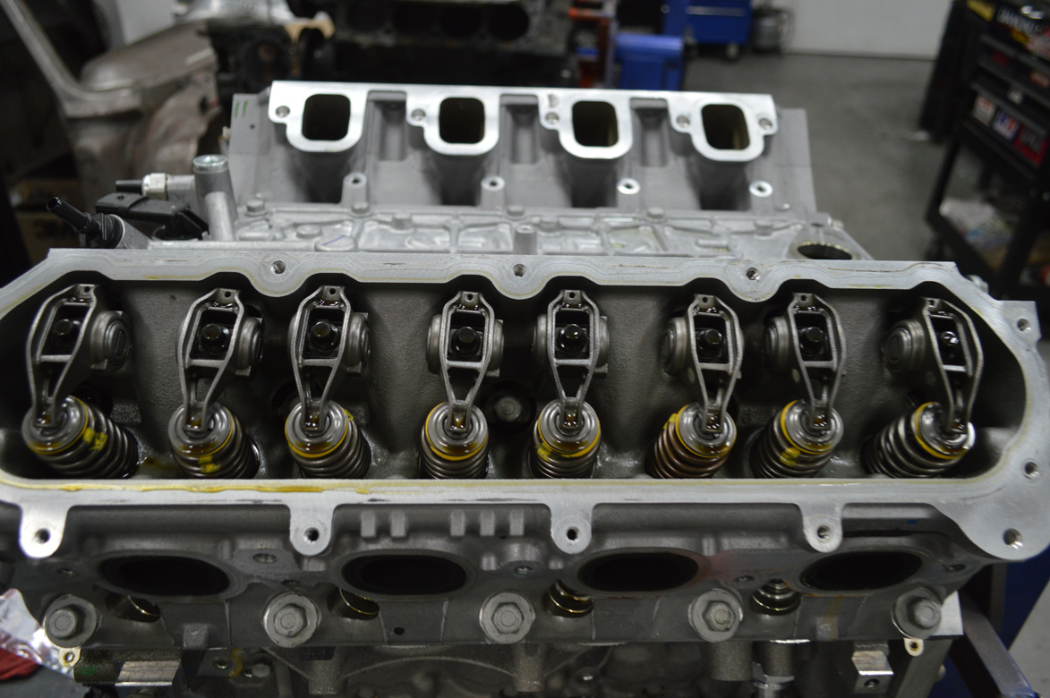
The real damage is lurking down below these guys…
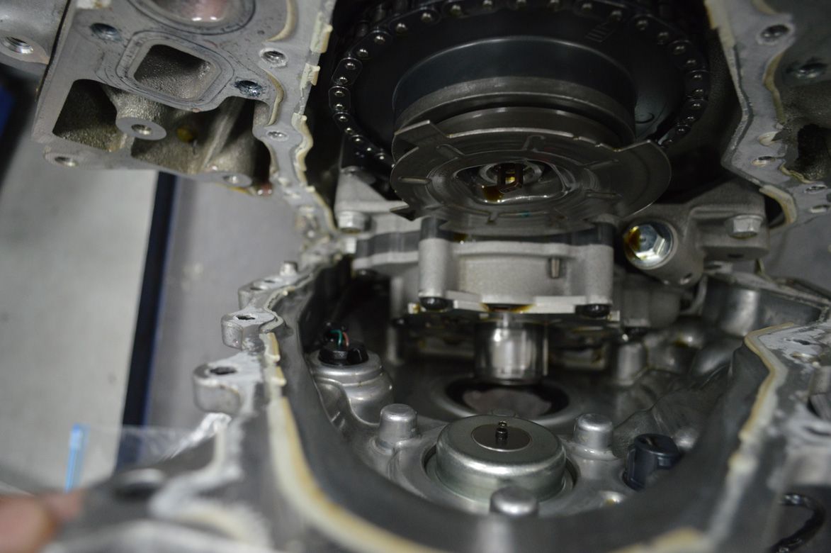
If you’re putting a cam in this will be a bane of your existence. The pigtail is mounted inside the timing cover and does not come out without taking the oil pan off. The connector is not accessible from inside the cover. You can carefully unclip it from the loom in the cover and there’ll be enough from to turn it out to pull the cam. z51 cars you can remove the pump, there is no pickup. Also you’ll be happy to know the 2 wires appear to be made out of a single strand of hair, and the connector on the pump sensor seems to be made out of glass. Goodluck.

Treat this like you are diffusing a bomb and you should be fine.
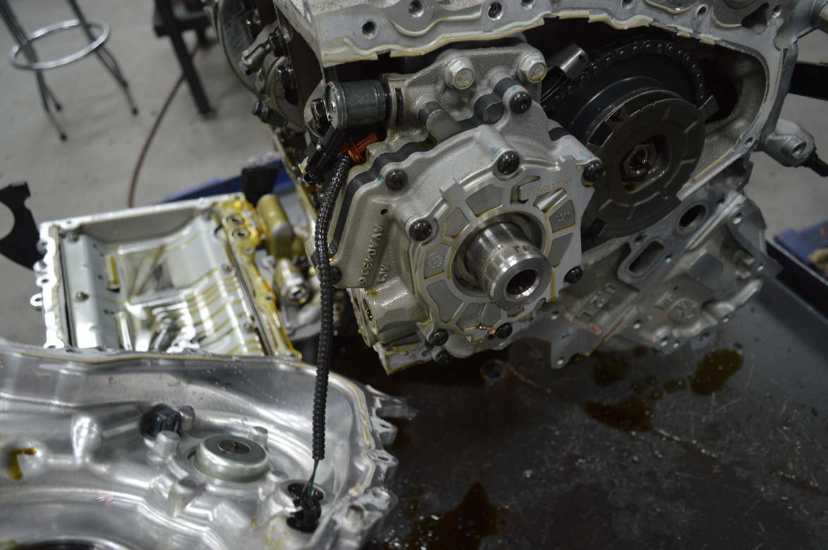
Note that the wires are roughly as thick as a single strand of hair. Good times.
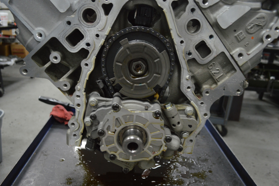
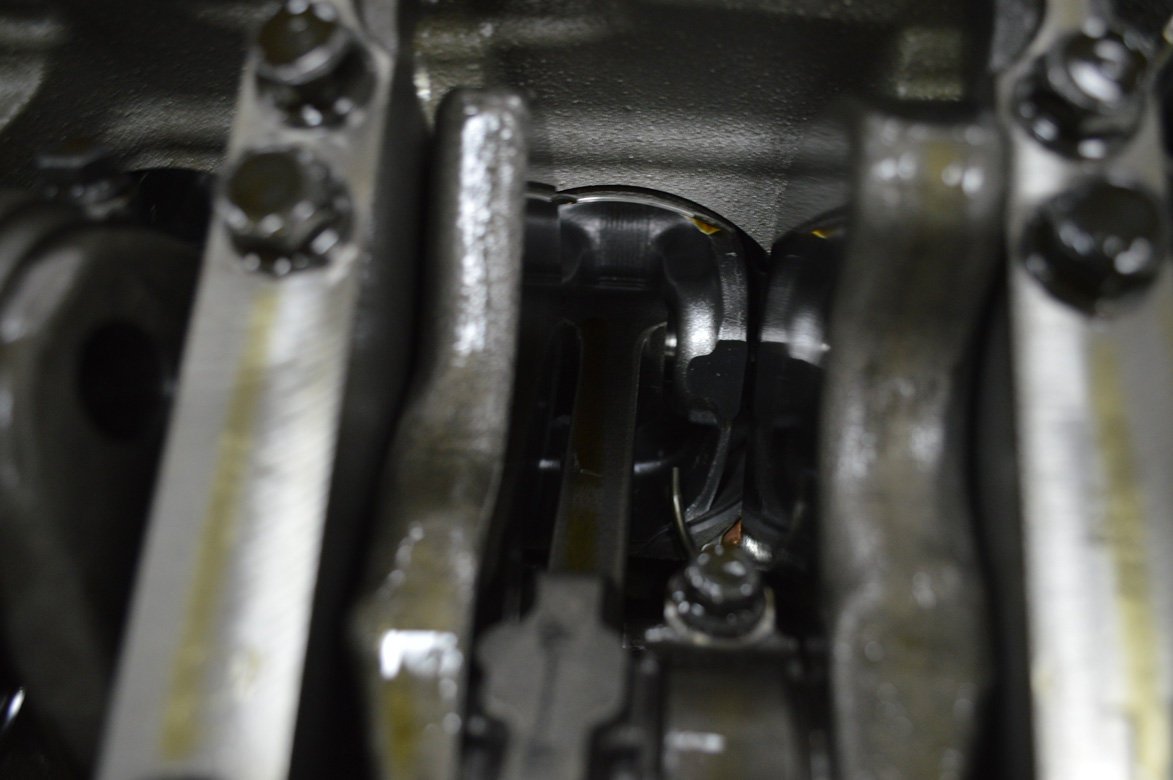
With the cover removed here’s what you’re looking at.

Rockers and pushrods gone…next go the head bolts.

The top, front, head bolt is an allen, it is also shorter than all the rest. I’m assuming they made it an allen so you don’t put one that’s too long in the hole and get no tq on the #1 head gasket.

This is why you shouldn’t learn to tune a Direct Injected Motor and a $80k car with a supercharger. OUCH!

Insert comment about “buffing out” here….
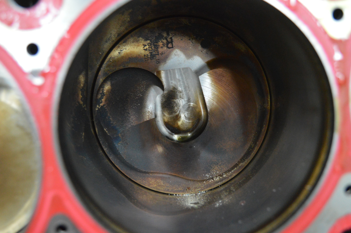
Note all the powder at the bottom of the hole. This thing either as a coke habit or something odd stuff started happening when that piece of the #2 piston decided to walk off the job.
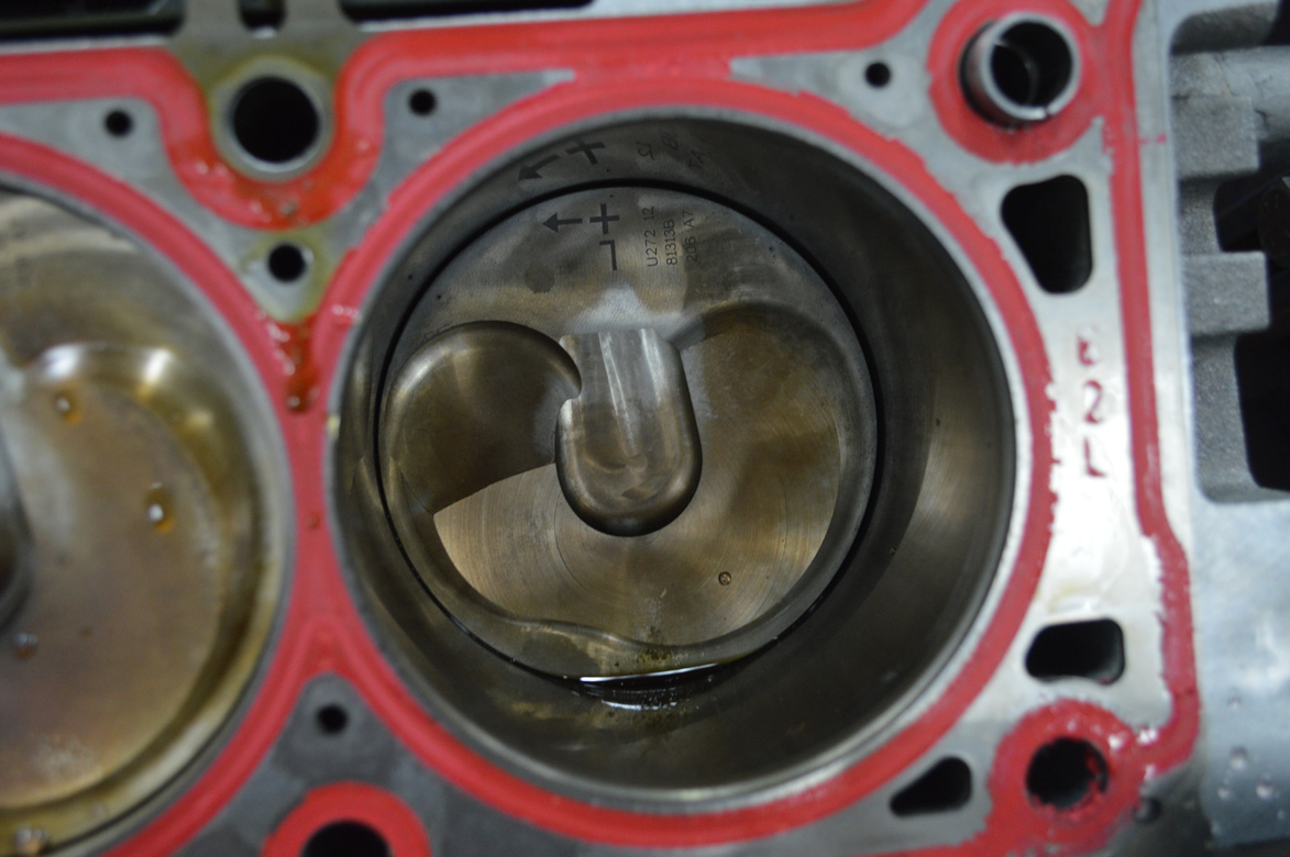
So as you saw the #2 is PHHHHUUU…T up. The #4 is powdered as well. The #7 has some deep scoring from trash, or a pinched ring. I’m leaving the forensic diagnostic for the machinist professionals. We will have pics once Steve tears it down.
This went from a combustion chamber to a potato masher when that piston broke apart. Pretty chewed up.

This combustion chamber will need some tig and surface work, it was unhappy. The rest will just need a cleanup.
Check out the piston squirters.

Squirty!

Cross bolted mains = strong like bull.
DOD actuators.
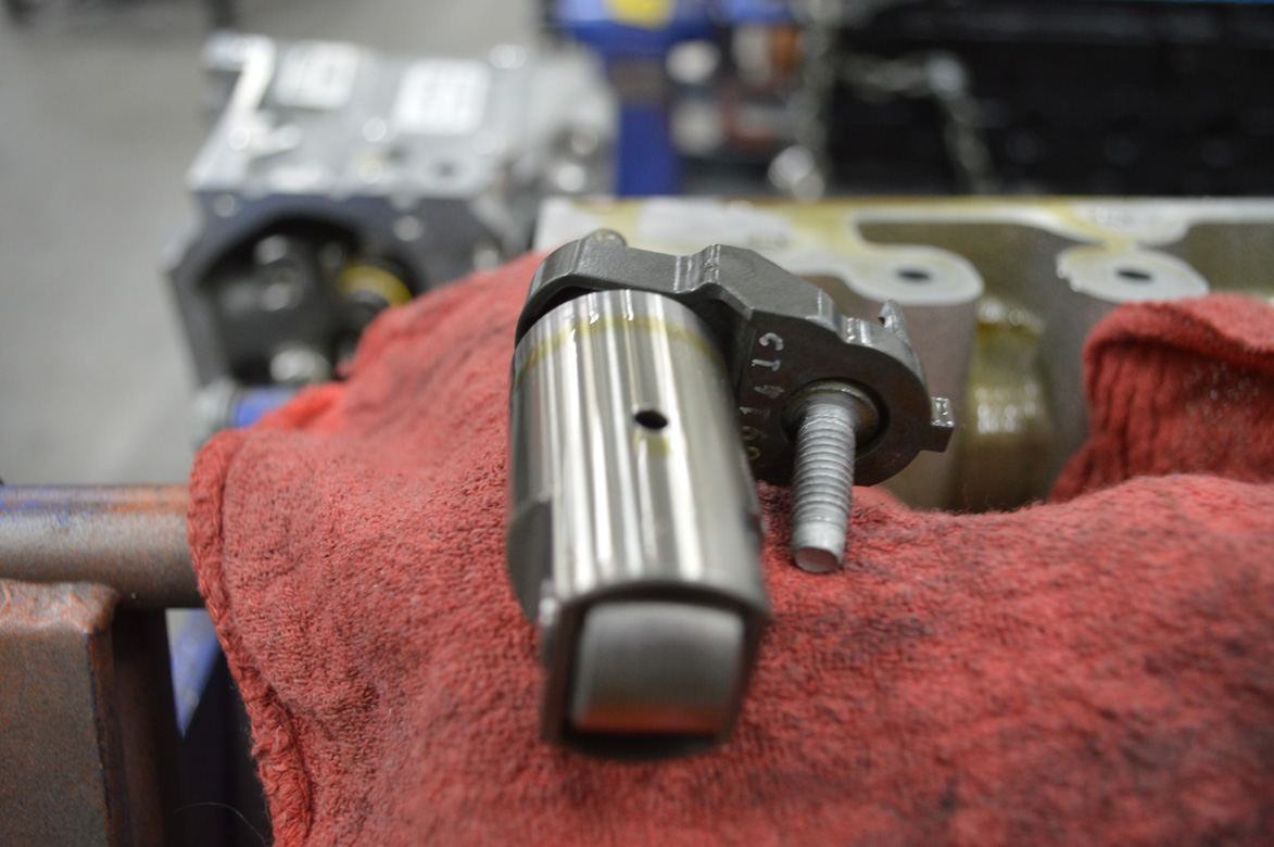
One big ass lifter? Nope, fuel pump pushrod, Given its size, there is serious pressure on this thing.
IT WILL BE A FEW DAYS BEFORE OUR NEXT UPDATE AS STEVE ASHWORTH RACING ENGINES WILL PULL APART THE ROTATING ASSEMBLY AND SEND US THE PHOTOS AND INFO OF WHAT HE FOUND!


Intriguing!
“Treat this like you are diffusing a bomb and you should be fine.”
lol
great story, don’t think I will be touching one of these,will take it to my friend Gary Grimes.
Its a fact, chassis dyno’s will tear your stuff up big time.
Its like look at pictures of a car crash. Cant wait for the next update.
eh seen worse a few rounds with the machinist and she will live again
you got very lucky here it could have very well gone out the bottom
I see this and cant help but think how Ford screwed up dropping push rods.
Those LS engines are pretty trick….
Really interesting article but I could do without drug references in a car site.
Since it is already apart, he might as well bump it to 417ci, add a camshaft, and CNC ported heads.
Time to visit Copart.com or LKQ.