


(By Loren Krussow) – I do not work in a state-of-the-art, high-tech shop. I wouldn’t knock it, though, for the purpose of making just one or two of something there are actually only a few advantages to having sophisticated equipment. Even the most advanced manufacturing facilities often still keep a manually-operated Bridgeport or similar mill in the corner for when a single part needs to be cranked out quickly.
While being the type of machine that has probably benefited most from modern controls, a mill in its basic form has changed little over the years and is one of the staples of metalworking. “Milling” just refers to removing material from an object by a spinning cutting tool—unlike, for example, a lathe with its stationary bit—and there are a variety of machine styles to do it. The vertical knee mill is the most common in manufacturing. It looks a little like a very heavy drill press and could be used as one, but is really made to do something a drill was never meant to: cut sideways. With a special cutting bit, super-stout construction, and a movable table to which the part to be machined is firmly fastened, it can be used to make virtually any shape that the cutter can fit around or into.
Typically the spinning cutting bit remains in a set position and the part is moved in a precise manner via the table, which is controlled by long screws with hand cranks on the end. Movement can be side-to-side (X axis), forward and back (Y axis) and up-down (Z). You can “interpolate” crude circular motion out of the X-Y such as how you’d draw on an old Etch-a-Sketch toy with the two knobs; computer-controlled machines can do this with precision. On our manual machine we’ve just added an attachment called a “rotary table” to crank out perfect circles by hand.
Wheel Spacers
I recently removed the trick modified-stock rear wheels on my bud’s Duster in the home garage and was disappointed to find a pair of cheapo cast wheel spacers. These are never a good sign, and as it happened, they not only didn’t bring the wheels out far enough to prevent the fat drag radials from rubbing on the leaf springs, but they were not of sufficient area to cover all the portions of the wheel intended to be clamped down to the brake drum. Just the act of tightening down the lug nuts was bending the wheel center out of shape as the most-center portion was being pulled into space instead of down onto a solid surface. Would you have thought you needed to watch for that? This wouldn’t be a problem with a cast-and-machined wheel but is a no-no with stamped steel.
A quick trip into the hi-perf mail-order catalog revealed nothing that appeared closer to solving the problem…the center holes were all too big, and besides, so were the stud holes. Any chance of using the shear strength of the stud to help hold the wheel in place is shot by having all that room around it and you’re left with only the friction between the wheel, spacer, and axle surfaces created by the lug clamping force. If we gotta use a wheel spacer, let’s at-least do this right and make our own part that’s big enough and has snug-fitting holes in the right places.
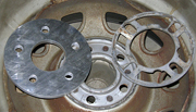
After band-sawing out a rough round shape from 3/8-inch-thick plate aluminum I stepped over to the mill. Using the rotary table and measuring calipers I plotted out the correct wheel bolt pattern and cut out five small pilot holes 72-degrees apart (360 divided by 5), then set about cutting a center hole which would fit close to the axle hub and cover all the area of the wheels which needed to seat. With that done I finished the bolt holes on a drill press and the outer diameter on a lathe. The whole process took about an hour-and-a-half.
![]()
These could have been made at home by tracing out the pattern from a brake drum onto a piece of aluminum and using a drill and hack saw but the mill was much faster and dead-on precise. More fun too! Bringing them home I was happy to see they fit well (there is always a chance one screwed up something and it has to be done over) and naturally we’ll slip these over a set of longer axle studs with open-ended lug nuts such as the tech guy at the track would rather see.

PS- When I first handed in this column, the BangShift guys questioned whether a wheel spacer should be made of hardened material. I would say that in the case of an “adaptor”-type spacer, which itself fastens to the axle or disc and then carries its’ own studs, material type would be vital. Catalog items are often advertised as 6061-T6 (hard) aluminum and need to be of a minimum thickness to be strong enough…I built a set for my ’59 Impala last year and used steel, I didn’t trust aluminum at all as I felt the studs might loosen.
In the case of the spacers I made, they are clamped between the brake and wheel only; they do not anchor their own fasteners. They get full-surface contact on the inside and all the wheel presents on the outside, which is pretty generous. Catalog items of this type are usually cast aluminum or zinc alloy, they stuff we expect carburetors to be made of, the spacers in the column are from cast aluminum “tooling plate” which is probably around equal hardness.
In any case the ones we made far exceed suitability for the purpose over the ones they replace, which were purchased from a wheel/tire store and indeed did cause lug-nut loosening and wheel damage.


