


(By Judson Massingill) – For decades, machinists and engine builders have been taught that when balancing a crankshaft, its counterweights should equal 100 percent of the rotating mass and 50 percent of the reciprocating mass. Machinists have used this formula to calculate bobweight for decades. While this technique works extremely well for the vast majority of both street and race 90-degree V-8 engines, the truth of the matter is that it’s nearly impossible to perfectly balance a crankshaft. That’s because the balancer cannot account for variables such as cylinder pressure, ring drag, rod length, counterweight phasing, engine rpm, stroke length, bearing friction, 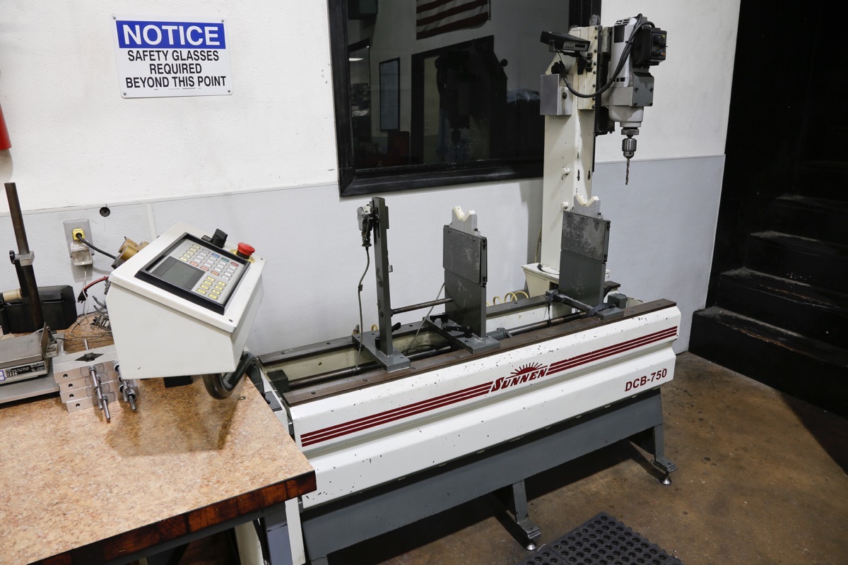 secondary vibrations, rocking couples, and static mass.
All of these factors play a dramatic role in overall engine balance, yet the traditional mathematical formula used for calculating bobweight completely ignores all of them. Instead, calculating bobweight is based strictly on measuring rotating weight and reciprocating weight, which is a gross oversimplification of the actual dynamic forces at play inside an engine that affect balancing. In other words, the traditional method of balancing a crank is, at best, an imperfect science. In fact, it’s not based on any real science or mathematics at all. It’s simply a technique based on trial and error that happens works well in most 90-degree, cross-plane V-8s.
Not surprisingly, as engine rpm and horsepower output increases, the traditional methods used to balance crankshafts become less effective. The big challenge for engine builders is figuring out how to work around these limitations to balance a crankshaft as precisely as possible based on the demands of each particular engine combination. This explains why many engine builders have experimented with techniques such as overbalancing, and why they’re often topics of intense debate.
Crankshaft balancing will always be a compromise, but to get a better handle on how to more effectively balance an engine, we will first outline basics of the balancing process. Next, we will briefly explain the shortcomings of traditional balancing techniques before finally exploring some of the advanced solutions top race teams have experimented with to prolong engine durability in extreme, high-rpm race applications.
Basics of Balancing
Properly balancing the rotating assembly in any engine build is paramount to maximizing performance and longevity. The typical hot rodder will walk into an engine shop and say they want their rotating assembly balanced to one or two grams. What they think they want you to do is to make sure all the pistons and rods weigh within a 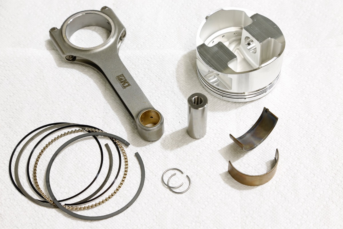 couple of grams of each other, but most quality aftermarket manufacturers already do that at the factory. The real goal of balancing a rotating assembly is to make sure that the crankshaft counterweights offset the rotating and reciprocating forces created by pistons and rods. With today’s lightweight pistons and rods, accomplishing this usually involves removing mass from the crank counterweights. With extremely long-stroke cranks that have shorter counterweights, or rotating assemblies with very heavy pistons and connecting rods, tungsten metal slugs can be pressed into the counterweights to increase mass.
The mass of the crankshaft counterweights should equal 100 percent of the rotating mass and 50 percent of the reciprocating mass. Determining how much mass to add or remove from the crank counterweights requires measuring all of the components in the rotating assembly individually on a high-precision scale. The pistons, rings, wrist pins, pin locks, and the small end of the connecting rods move up and down the bores, and comprise the reciprocating mass of a rotating assembly. An extra five to 10 grams is typically added to the reciprocating mass to account for the weight of the motor oil. The big end of the rods and the rod bearings rotate around the crankshaft centerline, and therefore represent the rotating mass.
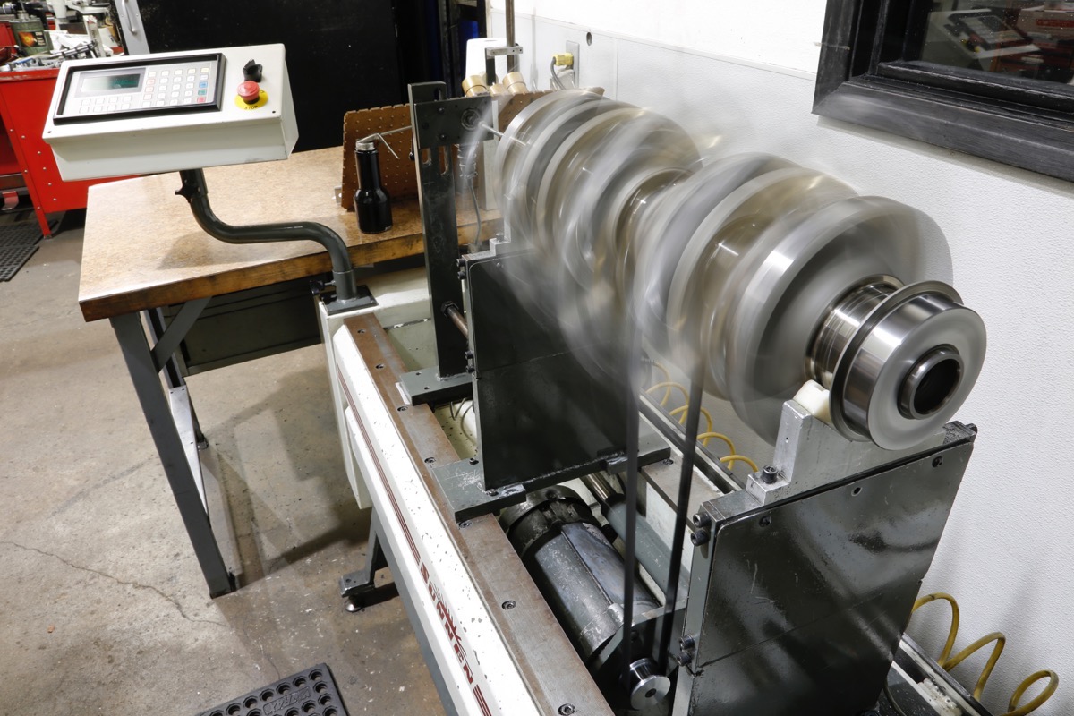
During the balancing process, bobweights are bolted to each rod journal to simulate the mass of a pair of pistons and rods. This is because each rod journal supports two sets of pistons and rods. After bolting the bobweights to the crankshaft, the balancer spins the assembly to roughly 750 rpm. Once the rotating assembly comes to a rest, the LCD display on the balancer indicates the amount and location of weight that needs to be added or removed as the operator slowly rotates the crank by hand.
Mass and Distance
Crank balancing equipment—such as the Sunnen DCB-750—measure the imbalance that exists in a rotating 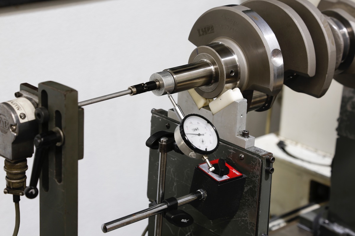 assembly in grams, but that’s just half the story. Simply stating that a crank is 60 grams out of balance isn’t sufficient. That would be like trying to use a map that had latitude co-ordinates, but no longitude co-ordinates. You have to specify both the mass of the imbalance and the location of that imbalance. In this case, the location of the imbalances is simply the distance of the imbalance from the crankshaft centerline.
To put the importance of this location into perspective, imagine swinging a rock tied to a string, then doubling the length of string and swinging it again. The rock would pull on your hand twice as hard even though its mass hasn’t changed. The same applies to a crankshaft, because the farther away a given unit of mass is from the crankshaft centerline, the greater effect it will have on the balance of the crank. For example, a crank that’s 20 grams out of balance three inches from the crank centerline is the same as a crank that’s 60 grams out of balance one inch from the crankshaft centerline. This is why the correct unit for measuring crankshaft balance is ounce-inches, not just ounces or grams.
Consequently, the distance any given unit of imbalance is located from the crankshaft centerline is just as important as the amount of imbalance itself. Interestingly, however, many engine shops don’t pay any attention to this critical detail. In fact, it’s possible for machinists to balance crankshafts for decades without even realizing the importance of specifying the distance of imbalance. The obvious question is, how can this be the case? The answer  is quite simple. The correction radius is the distance from the crankshaft centerline to the edge of the counterweights, and in most domestic V-8 engines, this figure is roughly three inches. When a shop orders up balancing equipment from Sunnen, the salesman sets up the machine using a three-inch correction radius, and trains the customer to add or remove material from the crank counterweights until the machine reads ¼ ounce-inch.
The problem with this approach is that once you factor in a three-inch correction radius, the crank is actually ¾ ounce-inch out of balance. So even though a machinist thinks they just balanced a crank to ¼ ounce-inch, it’s actually ¾ ounce-inch out of balance. The reason you can get away with it is because a crank balanced to ¾ ounce inch will run just fine in a typical street/strip motor, and it’s still far better balanced than a production engine.
How Good is Good Enough?
A rotating assembly can be balanced to varying degrees of precision, and a moderate-rpm street motor can get away with far more imbalance than a high-rpm race motor. So how close is close enough? The standard unit of measurement for crankshaft balancing is an ounce-inch. There are 28.34 grams in one ounce, so balancing to ½ 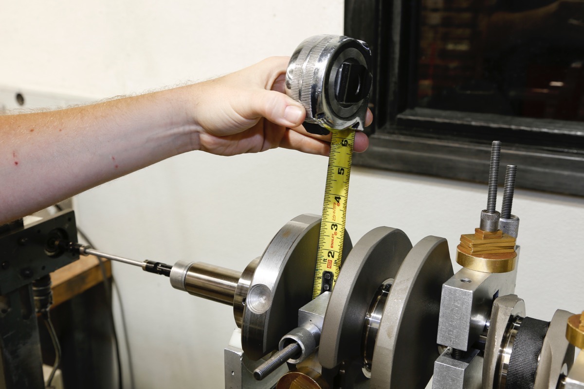
ounce-inch means that a crank has roughly 14 grams of imbalance one inch from its centerline. A factory 350 small-block Chevy is balanced to around two ounce-inches while a 7,000-rpm street/strip performance engine is usually balanced to ¾ ounce-inch. A very high-end race motor is usually balanced to ¼ ounce-inch, which is seen as the holy grail of balancing by engine builders. Even at ¼ ounce inch, the rotating assembly is still 7 grams out of balance an inch from the crankshaft centerline. That might seem like a lot, but a 10,000-rpm NHRA Comp Eliminator motor will run all season long when balanced to ¼ ounce-inch.
Nevertheless, with NHRA Pro Stock motors approaching 12,000 rpm, and NASCAR Sprint Cup motors turning 9,000-plus rpm for 500 mile race distances, the ¼ ounce-inch standard becomes less effective in extreme racing engines. The effect of rpm on an engine’s internal loads cannot be underestimated. As engine rpm increases, the tensile loads experienced by the connecting rods—and therefore the crank throws—increase exponentially. In other words, the tensile loads are four times greater at 5,000 rpm than at 2,500 rpm, and 16 times greater at 10,000 rpm than at 2,500 rpm. Likewise, as rpm increases, the effect of ring drag, bearing friction, and cylinder pressure (until peak torque is reached) on an engine’s overall balance increases as well.
With high rpm and big cubic inches comes serious horsepower, and the cylinder pressure generated along the way significantly impacts engine balance. For example, let’s say that an NHRA Pro Stock motor produces 3,000 psi of cylinder pressure on the conservative end of the spectrum. When combined with a 4.750-inch bore—which equates to 17.71 square inches of surface area on the piston crown—the result is over 50,000 pounds of force that’s transmitted into the block and rotating assembly during the power stroke. Clearly, merely balancing a rotating assembly to ¼ ounce-inch isn’t always enough in to accurately replicate the dynamic forces at play inside extreme race engines.
V-8 Nuances
The most fundamental factor to consider when balancing a race engine is why a 90-degree V-8 needs to be balanced in the first place. This particular configuration presents some inherent challenges. If a V-8 was flattened  into a horizontally opposed (boxer) configuration, the forces generated by a piston and rod at top dead center (TDC) on one bank of cylinders would be cancelled out by an opposing piston and rod at TDC on the other bank of cylinders. Since each bank of cylinders are phased 180 degrees apart, the forces cancel each other out perfectly and, therefore, do not need counterweights. Much like a flywheel, the primary purpose of the counterweights in these engines is to smooth out the rotational velocity of the crankshaft.
In contrast, when folding the block 90 degrees to create a V-8, the pistons and rods generate forces that travel in multiple planes. Since the forces generated by the pistons and rods on opposing banks in a V-8 cannot cancel each other out directly, they require counterweights to achieve proper balance. By positioning a counterweight phased 180-degrees away from TDC, they can effectively cancel out the movement of the piston and rod. Further complicating the situation is the fact that pistons and rods positioned at a 90-degree angle to each other transfer forces downward into the cylinder wall as well as at 45-degree angle to the crankshaft. The 50-percent reciprocating weight factor used during the balancing process attempts to compensate for these forces that are generated in multiple planes.
Center Counterweights
The textbook explanation of how counterweights offset rotating and reciprocating mass is easy enough to understand, but it’s at best merely a partial explanation of the actual dynamic forces at hand. That’s because most 90-degree V-8 crankshafts have only six counterweights, which means that the center two cylinders do not have any counterweights beneath them. Having two sets of pistons and rods whose bobweights are not accounted for requires adding this mass to the six existing counterweights. Although this approach works fine from a mathematical standpoint, the counterweights are not in the ideal position to cancel out the forces of the center two 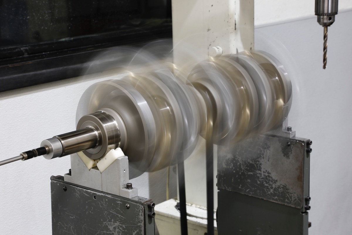 cylinders. Not surprisingly, this leads to extremely uneven bearing loads where the forces on the #2 and #4 main caps can be significantly higher than on the #1, #3, and #5 main caps.
Additionally, as horsepower and rpm increase, the rotational inertia of the counterweights combined with their positioning at the far ends of the crankshaft impart their own torsional loads into the crankshaft. This effect is similar to the torsional loads channeled into the crank by the flywheel and balancer in an externally balanced engine. Ultimately, these loads can lead to crank fatigue and crank failure.
Obviously, compensating from two missing counterweights by adding mass to the six existing counterweights is a less-than-ideal solution for high-rpm race engines. This explains why most custom billet crankshafts are built with center counterweights, bringing the counterweight total to eight. That said, merely adding two center counterweights is only half the battle. Even when using a crank with center counterweights, mass must also be removed from the front and rear counterweights to reduce the torsional loads imparted into the crank. In the past, many engine builders felt that the additional rotating mass of a center counterweighted crank would offset any potential horsepower gains resulting from evening out the bearing loads. However, dyno and track testing in recent years has proven that the decrease in bearing loads are so beneficial to horsepower output that they more than offset the additional mass.
Factors Unaccounted For
Among the dozens of variables that traditional balancing methods do not account for, peak engine rpm and horsepower output are two of the most significant factors. However, putting the extremely complex science of balancing into perspective requires examining variables such as ring drag, rod length, counterweight phasing, stroke length, bearing friction, secondary vibrations, rocking couples, and static mass in closer detail. Individually, each of these variables may not dramatically affect the overall balance of an engine, but cumulatively their effects are much more significant.
Weight and Power
Static weight is a topic that’s seldom discussed with regard to engine balancing. Even so, the ongoing quest to increase horsepower while reducing weight makes it a relevant topic nonetheless. If an engine weighed 1,000 pounds but only produced 100 horsepower, the effects of engine imbalance would be minor. That’s because a relatively small unbalanced force would have to move against a very heavy mass in order to create a vibration. On 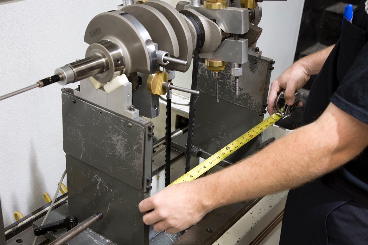 the other hand, if an engine weighed just 500 pounds yet produced 1,000 horsepower, any engine imbalance would be far more damaging. That’s because a very large quantity of unbalanced force would easily move against a relatively small mass to create detrimental vibrations. Engine builders are always striving to squeeze out the most horsepower while reducing engine mass as much as possible, and both of these objectives make an engine more vulnerable to harmful vibrations caused by imbalance. Since no engine builder in their right mind is going to decrease horsepower or increase weight to make their engines more resistant to imbalance, it’s imperative to find more practical methods of balancing race engines.
Internal Friction
Ring drag and bearing friction are very easy concepts to understand. During the balancing process, the crankshaft sits on two precision-calibrated stands that support the front and rear mains journals. The crank rides on plastic inserts fitted to the top of the stands, and oil is squirted onto the crank to reduce friction and to protect the mains. As such, the balancer sees just a miniscule fraction of the bearing friction a crank will encounter in a running engine. Likewise, the pistons aren’t actually attached to the crank during balancing, so ring drag is a non-factor.
On the other hand, when turning an assembled short-block over by hand, it takes about 30 lb-ft of torque to rotate the crank in a typical street/strip engine equipped with standard tension rings. Most of that required force is attributable to ring drag and bearing friction. Increase engine speed to 7,000 rpm, and the horsepower required to overcome that 30 lb-ft of drag is substantial. That resistance is channeled back through the crankshaft and block as unbalanced force.
Secondary Vibrations
Rotating and reciprocating forces generated once per every crankshaft revolution are defined as primary forces. Rotating and reciprocating forces generated twice per every crankshaft revolution are defined as secondary forces. While primary forces are easy to visualize, understanding secondary forces isn’t as intuitive. Imagine drawing a line on the cylinder wall precisely half way in between TDC (top dead center) and BDC (bottom dead center). Since the wristpin is positioned slightly below the piston crown, when the crank pin rotates downward to half the length of the stroke, the piston actually travels a distance greater than half the length of the stroke. As a result, the piston accelerates away from TDC toward the halfway point more quickly than it accelerates from the halfway point toward BDC. The same applies as the piston reverses direction back up the bore. In other words, the piston’s rate of acceleration increases once it passes the halfway point on its way back up toward TDC. This disparity in piston acceleration creates an upward vibration that occurs twice per crankshaft revolution, which is where the term secondary force (or vibration) comes from.
Fortunately, since each of the four crankpins in a cross-plane V-8 are phased 90 degrees apart, there are always pairs of pistons moving through different phases of the crankshaft rotation cycle. As crank first crank pin (from the front) rotates downward from TDC to 90 degrees after TDC, the third crank pin travels from 90 degrees before TDC to TDC. Likewise, as the second crank pin rotates downward from 90 degrees after TDC to BDC, the fourth crank pin travels upward from BDC to 90 degrees before TDC. Consequently, the fast downward movement of the first crank pin cancels out the fast upward movement of the third crank pin, and the slow downward movement of the second crank pin cancels out the slow upward movement of the fourth crank pin. This effectively cancels out the secondary forces.
Unlike many of the other variables discussed thus far, secondary forces aren’t ignored by traditional balancing methods. They simply don’t seem as important in a cross-plane V-8 since this particular engine configuration naturally cancels out secondary forces.
Rocking Couple
One downside of the cross-plane V-8 configuration is that the design of the crankshaft creates a see-saw rocking motion from front to back. This is because the first and second crank pins move upward at the same time, while the third and fourth crank pins move downward at the same time. Since the orientation of the front two crank pins and rear two crank pins reverse every 180 degrees of rotation, the crank rocks up and down like a see-saw. This rocking couple is yet another force that the counterweights are responsible for cancelling out.
Similarly, each pair of rods share a common crank pin in a 90-degree V-8, which requires staggering their positioning to prevent them from running into each other. This offset creates another rocking vibration that’s difficult to eliminate. These rocking couples can be eliminated through some clever engineering, but they aren’t addressed directly, as cancelling them out usually requires completely redesigning the short-block components.
For example, V-twin engines often utilize a blade-and-fork rod arrangement. In this type of setup, one rod is forked while the adjacent rod fits in between the “prongs” of the neighboring rod’s fork. This allows both rods to share a common crank pin and to also be positioned on the same vertical plane, thus eliminating the rocking vibration. Domestic V-8 manufacturers would have probably experimented with a similar design if it was worth the effort, which suggests that this particular rocking couple is only a minor issue. Even so, it’s still one of dozens of variables that can impact balancing in some way or form that isn’t directly addressed.
Cylinder Pressure
Granted that the cylinder pressure pushing down on the rotating assembly is immense during the power stroke, but that’s not the only cycle during the four-stroke process that affects engine balance. As an engine cycles through the intake, compression, power and exhaust strokes, the cylinder pressure is constantly changing. Changes in throttle position and engine rpm create even larger swings in cylinder pressure.
 To illustrate the point, imagine a scenario where a driver winds an engine out to 9,000 rpm at wide-open throttle, then suddenly snaps the throttle shut while stepping on the clutch. Not only has the rpm suddenly dropped, but the engine has transition from having tens of thousands of psi of positive cylinder pressure during the power stroke to now having negative cylinder pressure on the intake stroke. The resulting shock would send quite a bit of unbalanced force through the motor. Although this is an extreme and contrived example, pushing and engine through far lesser extremes still subjects it to large changes in cylinder pressure that adversely affect balancing.
Rod and Stroke Length
Rod-to-stroke ratio has long been debated regarding its impact on horsepower and torque. What isn’t nearly as controversial is its impact on balancing. As the length of the stroke increases, the rod angularity increases as well. The same applies to when the stroke length remains the same, but the rod length is reduced. Any increase in rod angularity increases the side loads transmitted into the cylinder walls, thus increasing the unbalanced forces inside an engine. In other words, the lower the rod-to-stroke ratio, the higher the magnitude of unbalanced force acting upon the engine. Consequently, a 400 small-block Chevy with 5.565-inch rods and a 3.750-inch stroke (1.48:1 ratio) will generate greater imbalance than a 302 small-block Chevy with a 5.700-inch rods and a 3.000-inch stroke (1.90:1 ratio), since the 400’s rods oscillate in a larger arc.
Measuring Rod Weight
Since a connecting rod moves in both a reciprocating and rotation motion, it is the wildcard in the overall balancing equation. Determining which section of a rod reciprocates and which section of a rod rotates is a tricky proposition, yet it’s critical to establishing the bobweight when balancing. The center of the wristpin is pure reciprocating mass, while the center of the rod journal is pure rotating mass. Consequently, any section of the rod in between these two points both reciprocates and rotates to varying degrees.
Breaking things down even further, the section of the rod beam directly beneath the wrist pin oscillates in a very small arc, which means that its reciprocating motion is far greater than its rotating motion. In contrast, the big end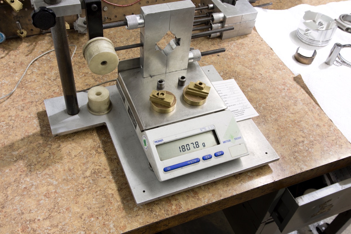 of the rod oscillates in a very large arc, which means that its rotation motion is far greater than its reciprocating motion. Therefore, the upper sections of the rod beam (closer to the wrist pin) reciprocate more than they rotate, while the lower sections of the rod beam (closer to the crank pin) rotate more than they reciprocate. At the half-way point between the big and small rod ends, 50 percent of the rod movement reciprocates, and 50 percent of the rod movement rotates.
Interestingly, the conventional method of measuring the weight of a connecting rod takes none of these facts into account. Measuring the weight of the big and small ends of the connecting rod independently involves placing it in a simple fixture that supports each end on a stand. One stand rests on the scale, while the other stand rests on the table. To weigh the big end of the rod, it’s placed on the stand resting on the scale. The small end of the rod is raised or lowered on its adjustable stand (resting on the table) until the rod is horizontal. To weigh the small end of the rod, the entire procedure is repeated after reversing the orientation of the rod 180 degrees.
The fundamental flaw with this method is that it assumes the center of gravity is the half-way point on the rod where 50 percent of rod movement is reciprocating, and 50 percent of rod movement is rotating. If this was true, the half-way point would be heavily biased toward the big end of the rod, since in reality the big end is much heavier. To illustrate the point, imagine attaching heavy magnets to the big end of the rod. According to the conventional method of weighing a rod, the resulting shift in center of gravity would also change the reciprocating weight dramatically, when clearly this isn’t the case. Similarly, since the center of gravity of a rod is much closer to the big end of the rod than the small end of the rod, it assumes that the majority of the rod beam represents rotating mass. However, even sections of the rod beam very close to the wristpin oscillate in a rotating motion, so this assumption is also inaccurate.
Over/Under Balance
Considering the inherent problems associated with weighing a rod off of its center of gravity, suspending it by a string at its geometric center, then weighing the big and small ends, yields far more precise results. Using this method, the measured reciprocating weight of the rod would decrease, while its measured rotating weight would increase. The net effect is a three percent increase in bobweight. (Jud: I’d like to include some real numbers here once we’ve had a chance to measure a real set of rods in the shop using the described method).
Interestingly, this increase in bobweight seems to support the practice of overbalancing a crankshaft. Many engine builders claim that adding an extra one to five percent of mass to the reciprocating weight helps even out bearing wear. For example, setting up the bobweights to 100 percent of the rotating weight and 53 percent of the reciprocating weight is the equivalent of overbalancing a crankshaft by three percent. Let’s say that an LS1 rotating assembly calls for a bobweight of 1800 grams. In this example, the rotating weight is 880 grams and the reciprocating weight is 920 grams. Adding three percent to the reciprocating weight equals 947.6 grams, which represents an overall increase in bobweight of 27.6 grams, or 1.5 percent.
Nevertheless, it would be overly presumptuous to declare the validity of overbalance based on this simple example. While overbalancing is common is race engines, some engine builders have found no benefits to overbalancing. Meanwhile others claim that underbalancing a crank to less than 50 percent of the reciprocating weight improves bearing wear. The only thing that is certain is that there is no consensus amongst engine builders regarding the benefits of over- or underbalancing a crankshaft. Ultimately, the traditional method of measuring the weight of a connecting rod based on its center of gravity is far from precise, but it tends to work well enough in most engine applications.
Potential Solutions
Given all the variables that go unaccounted for during the balancing process, how can engine builders improve 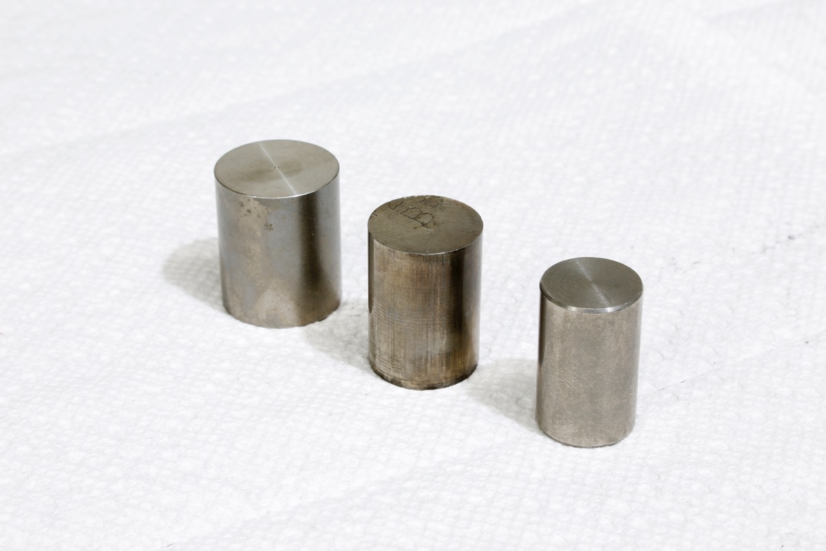 upon standard balancing techniques in high-rpm, big horsepower applications? Racers and industry experts have been attempting to solve this riddle for decades. Through a combination of incredibly advanced technology and good old fashioned trial and error, engine builder are making steady progress in navigating these murky waters.
Since GM, Ford, and Chrysler (or any other OE manufacturer) have resources far beyond that of even a top-tier engine shop, it’s not surprising that they have developed incredibly advanced tools to assist with the balancing process. To eliminate all the variables that a standard balancer can’t measure, the world’s ultimate balancer would allow running an engine on the dyno at idle, part-throttle, and WOT. The OEs aren’t there quite yet, but GM has taken a stop in the right direction.
At GM LS7 engine assembly plant, the company utilizes dynos that spin the motor to approximately 2,000 to 3,000 rpm. A series of sensors attached to the motor measure the imbalance, and a technician then adds or removes mass from the flywheel as necessary. While GM performs an initial baseline balance before the engine is assembled, this final step allows fine tuning the balance beyond what’s possible using standard balancing equipment.
It’s important to note that on the engine isn’t running under its own power during this balancing process. Instead, it’s the dyno that’s rotating the engine over. While this makes it impossible to directly measure the effects of cylinder pressure during the power and exhaust strokes, the dyno can still replicate the forces generated during the intake and compression strokes. Equally as important is the dyno’s ability to measure the effects of ring drag, bearing friction, counterweight phasing, rod-to-stroke ratio, and static weight on balancing.
Counterweight Phasing
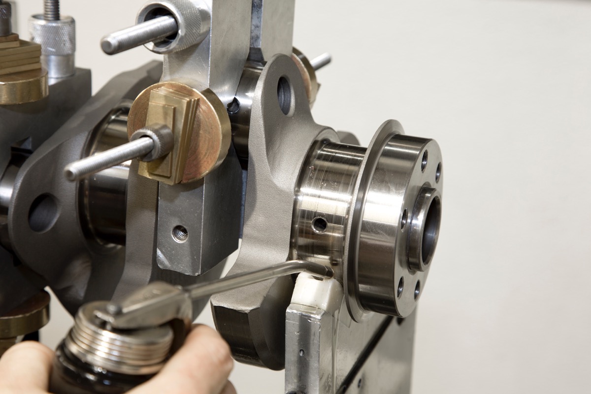
Considering that the counterweights are the components that are actually responsible for balancing the rotating and reciprocating forces inside an engine, logic says that refining the balancing process starts with the counterweights. When comparing an off-the-shelf cast or forged crankshaft to a custom billet crank, engine builder often attribute reduced engine vibrations and bearing wear to reduced crank flex and the addition of the center counterweights. These are valid points that shouldn’t be ignored, but it’s also possible that much of the improvements are attributable to the actual positioning of the counterweights in relation to the rod journals.
Counterweight positioning, or phasing, is something that’s seldom discussed, so it’s a term that probably doesn’t register with most people. To get a better handle on this concept, imagine looking at a crank from the head-on profile with the snout up front and the rear main in the back. The counterweight phasing is simply where the counterweight is positioned in relation to each rod journal. While most literature on balancing states that the counterweights are positioned 180-degree out from the rod journal, no one has bothered defining what 180-degrees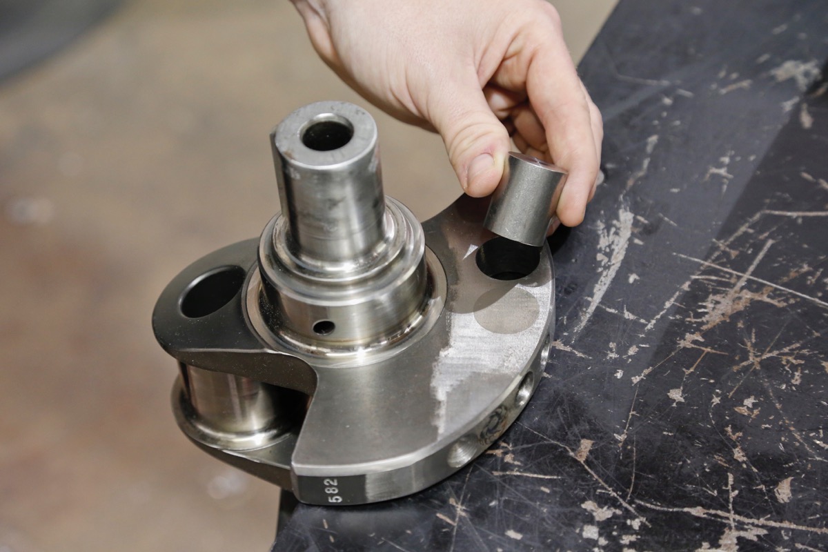 out actually means.
For example, if the entire mass the counterweight was moved clockwise by several degrees, most of its mass would still be 180-degrees out. Likewise, if the entire mass the counterweight was moved counter-clockwise by several degrees, most of its mass would still be 180-degrees out. Obviously, when carving out a crankshaft from a single piece of billet steel, custom crank manufacturers like Bryant or Windberg can position the counterweights wherever they want in order to experiment with its effects on balancing. Companies on the cutting edge of technology usually aren’t willing to disclose their trade secrets, so whether they determine counterweight phasing based on mathematical formulas, trial and error, or both is a mystery.
Of course, all this talk about counterweight phasing assumes that it has positive effects on crank balancing in the first place. That said, the negative effects of positioning the counterweights in the wrong place have clearly been demonstrated in real-world testing. In extreme situations, the positioning of the counterweights can be so far off that even after balancing to ¼ ounce-inch, a motor can rattle itself to death and destroy the bearings. Although this doesn’t happen often, every now and then a defective crank will slip past a manufacturer’s Quality Control department, and the carnage they create leaves people scratching their heads. I’ve personally witnessed this happen on the dyno.
If poorly placed counterweights can wreak havoc on engine balancing, this seems to suggest that ideally placed counterweights will even out bearing loads and prolong engine durability. Evidence certainly suggests that this may be the case. Although it flew under the radar at the time, Ford experimented with phasing the counterweights in different positions during the ‘60s in its Le Mans road racing engines.
Similarly, one of my graduates that works for a NASCAR Sprint Cup team was tasked with carrying out a similar experiment. In it, he removed material from the leading edge of the counterweights, and added the same amount of material back onto the trailing edge of the counterweights. This effectively changes the counterweight phasing in relation to the rod journal. Not surprisingly, my anonymous source wasn’t at liberty to discuss the results of this experiment, but the amount of time and money one of the top engine shops in the country was willing to invest in this research suggests that the potential benefits of phasing the counterweights just right are significant.
Lab Testing
Based on the aforementioned examples drawing any definitive conclusions regarding the effects of counterweight phasing on engine balance isn’t possible. It’s hearsay at best. Fortunately, engineers at North Carolina State University conducted extensive lab experiments to test this theory in the late ‘90s on a NASCAR Sprint Cup small-block Chevy. The results can be read in SAE paper 960354, and the results are eye-opening to say the least. By changing the position of the counterweights while leaving their overall mass relatively unchanged, the engineering team of Robert Sharpe, J.W. David, and Erik Lowndes reduced average bearing loads by 74 percent, and peak bearing loads by 41 percent.
The primary focus of the lab testing was to test the effects of counterweight phasing on engine balance while also accounting for cylinder pressure. During the experiment, the overall mass of the counterweights was left relatively unchanged, but the center of mass—and therefore the location of the counterweights—were optimized to reduce bearing loads. To simulate the operating range in a typical Cup race, the testing procedure varied engine rpm  between 5,200 and 7,200. The key piece of data gathered during the test was comparing the bearing loads generated with an unmodified racing crankshaft to the loads generated with the modified crankshaft. Since bearing loads peaked at 6,200 rpm, the following figures were measured at that point.
With the unmodified crank, the baseline average bearing loads on main caps #1 through #5 read 19.89-, 24.20-, 10.94-, 27.72-, and 22.65 kilonewtons of force, respectively. Keep in mind that one kN equals 240.8 pounds of force, which is significant to say the least. With the modified crankshaft, those readings plummeted to 5.97-, 9.76-, 10.90-, 9.96-, and 6.08 kN, respectively. While the load on bearing # 3 didn’t change much, the load on all the other bearings was reduced 60- to 74 percent.
The reduction in maximum bearing load was extremely impressive as well. With the unmodified crankshaft, the baseline peak bearing loads on main caps #1 through #5 registered 38.59-, 45.15-, 27.13-, 48.75-, and 41.60 kN, respectively. As expected, main caps #2 and #4 experienced substantially greater loads, which isn’t surprising since bearings #2 and #4 typically experience the most wear. After modifying the crankshaft, the bearing loads dropped to 25.40-, 28.15-, 26.40-, 28.62-, and 25.62 kN, respectively. With the exception of the center bearing, this represents a 34- to 41 percent reduction in peak bearing loads. Equally as revealing is how effectively repositioning the counterweights evened out the bearing loads across all five main caps. With the modified crank, bearings #2 and #4 are no longer taking the brunt of the abuse, which can only lead to increased crankshaft longevity.
Conclusion
Although the cited SAE paper doesn’t go into great detail on exactly where the counterweights were repositioned to, which could have been intentional, the changes in bearing loads are staggering. Equally as surprising is the fact that the center of mass of the counterweights was only moved a few millimeters to optimize crank balancing. This begs the question, why does altering counterweight phasing affect overall balance and bearing loads so profoundly? Crank flex could be the key.
There’s lots of talk about how balancing affects crank flex, but very little talk about how crank flex might affect balancing. Consider that, when measured from front to back, a crankshaft can flex quite few degrees (Jud: I’d like to add a specific number of degrees of flex, but don’t know figures to use). It’s already been established that changing the counterweight positioning just a few millimeters can dramatically affect balance. That said, if crank 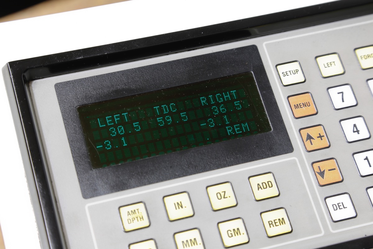 flex caused the position of the rod journal to change in relation to the position of the counterweight, it’s conceivable that this flex would have some degree of impact—or perhaps even a very large impact—on balance.
Even if a crank did not flex between the rod journal and counterweight, or if this flex was too insignificant to affect balance, the crank can still flex torsionally along its own centerline. In this scenario, the location of the rod journals in relation to one another would change. For example, instead of rod journals number 1 and 2 being positioned 90 degrees apart, crank flex could squeeze this dimension together just a tiny bit to 87 degrees, or spread it apart to 93 degrees.
Minor flexing of just a few degrees in either direction may seem inconsequential. However, the fact that secondary balance is dependent upon maintaining consistent 90-degree phasing between the rod journals cannot be overlooked. Flex along the crankshaft’s rotational axis could potentially compromise a cross-plane V-8s ability to naturally cancel out secondary vibrations. Yet another factor to consider is that if this type of flex did in fact upset the secondary balance, a shorter connecting rod could conceivably make things worse since it would accelerate the piston away from TDC even more quickly than a longer rod.
Perhaps someday technology will exist that allows bolting a running engine to a balancer under all operating condition, thus eliminating nearly all the variables that can affect engine balance. Until then, modifying counterweight phasing seems to be one of the most effective methods of optimizing balance in a high-rpm racing engine.
About the Author
Judson Massingill is the Co-Founder and Head Instructor of the School of Automotive Machinists in Houston, Texas. Along with his wife Linda, he runs one of the most highly respected vocational engine building schools in the country. From NASCAR Sprint Cup to NHRA Pro Stock, SAM graduates occupy the ranks of the industry’s top race teams. Legendary engine shops such as Hendrick Motorsports, John Force Racing, Roush-Yates Racing Engines, Jon Kaase Racing Engines, Penske Racing, Cosworth Engineering, Don Schumacher Racing, and Cagnazzi Racing all rely on SAM graduates to stay at the front of the pack.
The school’s unique program focuses strictly on the art of building race engines, and encompasses everything from short-block machining and assembly to cylinder head porting and design to CNC programming and machining. In 2012, SAM students and instructors captured the coveted Engine Masters championship, beating out some the best professional engine builders in the industry. SAM’s 1999 Camaro SS project car runs 8.0 quarter-mile e.t.’s at 175 mph, and has racked up three NMCA LSX Challenge championships in the All Motor class. In addition to his duties as SAM’s head instructor, Judson serves as a tech consultant for leading publications such as Hot Rod, Car Craft, Super Chevy, and Chevy High Performance magazine.
Source
School of Automotive Machinists;
Houston, TX; 713.683.3814;


Really great write up, made me think a lot about the amount of variables that occur with each cycle of the firing order and the balance or imbalance with the assembly as a whole.
WOW
excellent information! More please!! THANKS!