


- Introducing Project Buford T Justice – Our 1987 9C1 Chevy Caprice – The Adventure Begins!
- Project Buford T Justice: Our Cop Car Cruises Home and Then We Beat on It!
- Driveway Tech: Bodywork on Buford T Justice – We Close Our Roof Hole For Fun and (NO) Profit!
- Project Buford T Justice Hits the Strip with Some Pretty Shocking Results!
- Project Buford T Justice Hits the Dyno and Goes KABLOOEY! CARNAGE VIDEO INSIDE!
- Project Buford T Justice Will Be Saved For About A 100 Bucks With a 15 Year Old Transmission
- Project Buford T Justice Update: The Trans Thrash is ON!
- Buford T Justice Update: It Lives Again Thanks to a Down and Dirty Driveway Thrash and Junkyard Parts
- Buford T Justice, Our 1987 9C1 Chevy Caprice Goes Through Final Testing Before the Upgrades Begin!
- Buford T Justice 9C1 Update: The Parts From Hotchkis, Cragar, AFCO, and Mickey Thompson
- Update: Hotchkis Suspension & AFCO Bushings Transform Our 9C1 Caprice
- Buford Update: Our 9C1 Caprice Gets Real With Mickey Thompson Tires and Cragar Wheels
- Driveway Tech: How To Swap A Jeep Steering Shaft Into Your GM B-Body or G-Body Car With A Trashed Rag Joint
- Buford Update: We Flog The Suspension, Unveil a Mountain of Speed Parts, Spill Our Wild Drag Strip Plan
- Project Buford T Justice Update: Drag Strip Thrash Squashed By Ma Nature – We Learn Stuff – Plan B!
- Project Buford T Justice Quick Update: Where The Hell Has Our 9C1 Caprice Been?!
- Project Buford T Justice: We Go On Hot Pursuit Of Horsepower-Our 9C1 Caprice’s 350 Gets A Slap!
- Buford T Justice 9C1 Caprice Update: Metal Fab,Head Work, A Good Surprise, An Awful One
- Buford T Justice Update: Headers, Cheap LS Technology, New Valvetrain Parts, More Compression, Fun!
- Buford T Justice Update: A TCI 700R4 And Breakaway Torque Converter Get Our 9C1 Caprice Shifty!
- Buford T Justice Update: A Very Frustrating Day On The Dyno And How We’re Planning To Fix It
- Project Buford T Justice Update: Where Has Our 9C1 Caprice Been Hiding?
- Buford T Justice Update: We Install A First Gen Chevelle Flowmaster Kit On Our 9C1 Caprice!
- Project Buford T Justice: Our Caprice 9C1 Gets The Shaft! A Dynotech Drive Shaft That Is!
- Project Buford T Justice Our 1987 9C1 Caprice Hits The SCCA Autocross – Photos And Video!
- Project Buford T Justice Update: We Finally Give Our 1987 9C1 Caprice A Cheapo Nose Job!
- Project Buford T Justice Update: We Hit The Strip Again With More Power! (W/Video)
- Buford T Justice Update: We Bolt On Power From Trick Flow And Snappy Looks From Trans Dapt!
- Project Buford T Justice Update: Where The Heck It’s Been And Where The Hell It is Going –
- Place Your Bets For A BangShift Shirt! Buford T Justice Is Hitting The Dyno With This Engine One Last Time – Guess The Power And Win
- Project Buford T Justice: The Long Arm Of The Law Gets Longer With A Stroker Build – 388ci Of Budget Fun

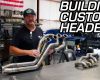
With the heads off the engine, I was able to lay the headers in and kind of mock them into place where I thought they would be when bolted up. These are Flowtech part number 11100FLT. They are 1-5/8 primary tube full length headers, uncoated. Retail from Summit is about $130.00. They are not specific to the Caprice but are listed as fairly generic "passenger car" headers. I did have to do a little metal work with the grinder to make them happy.

I am not sure if all Caprice models are fitted with these front frame braces but at least 9C1 cars are. Rather than chopping them out, I spent about 10 minutes per side with an angle grinder and contoured them so that the header would fit properly inside of them when bolted up. It was quick work with nothing in the way.

Here's a look at the massaged brace on the driver's side of the car. Again, it was a quick operation and I'm not sure if every Caprice would have this issue or just the cop models. That Motorcraft oil filter was installed by the previous owner. It has since been replaced by an AC Delco unit.

While I had a couple of days to wait for parts, I decided to make the engine look a little less horrible and clean the valve covers before slathering them in a coat of paint.

They spiffed up pretty nice for a pair of stock center bolt valve covers. Maybe I'll add something more racy after the engine starts doing something other than taking up space.

I also went ahead and stripped, painted, and plugged the factory water neck. The brass plugs were cheap from the home improvement store and look better than the nubs that were jabbing out of the thing before.

Turning to my high tech parts washer, I cleaned all of the bolts and got ready for the parts and pieces to arrive I would need to button the engine back up with.

Using this cool depth gauge I borrowed from my father in law I determined that the pistons were down pretty deep in the hole at top dead center. This is a result of the engine having been rebuilt and the rebuilder pistons have a shorter compression height than stock ones to compensate for the larger bore. The dished pistons were down about .050 in the hole. With the lumpier than stock cam heading into the engine, more compression was a necessary thing. The guys at the machine shop had helped some with the 12-thousandths they milled off the bottom of the heads and I was going to tighten things up a little more with a thinner head gasket.

After kicking a bunch of ideas around with the guys on the BangShift forum, I went with Fel-Pro PN 1094. This is a rubber coated, stainless steel shim gasket that has a thickness of .015 when compressed under the head. Retail on these babies is about $35.00 a pop from your favorite online speed shop.

As they are rubber coated, no special block prep is necessary and I installed them "dry" so to speak after cleaning everything up. Having run the numbers through about 20 different compression calculators, the engine should be a hair over 9.2:1 compression with these gaskets and the slightly milled down heads. Certainly not idea, but far better than the mid-8s it had stock.

To clean everything up, I used a brass bristle brush on the end of my power drill. The brass is nice and soft and I was able to really get things cleaned up nicely on both sides of the block before plopping the gaskets on.

I also went ahead and laid the headers into the engine bay so I wouldn't have to wrestle them in with the head on. It was a little bit of a pain in the ass to jockey them around while torquing the heads but they were right there to be bolted up when done. When these heads come off again (spoiler alert...they will be coming off again) I think I will use the same strategy.

With everything clean, it was time to slap the gaskets on and then drop the iron heads down on top of them.

I stuck both heads on and then went through the standard issue torquing procedure. I reused the head bolts and there was no real drama during this part of the process.

Hey, you have to admit that it was at least starting to look better than the greasy mess it was before at the dyno...right?

With the heads secured, I bolted up the headers and they fit great with my previous grinding work.

I then set my sights to the center of the mill. First, I put my freshly painted valve covers on, which was kind of a safe guard to keep me from dropping anything into an oil drain back passage or something. I did neglect to cover the intake and exhaust ports mostly because I ate a lot of glue as a kid.

I decided to install the new COMP roller lifters and Magnum series rocker arms and pushrods while the engine was this far apart. I also planned on installing some GM Performance LS-style lifter guides which would hold the lifters up and allow a cam swap to be done at the dyno without pulling the intake. Trick! The process began with pulling the lifter spider from the center of the valley.

Three quick bolts and the spider was up out of the way. I took the opportunity to chase my kids and wife around with the oily thing because I get a lot of enjoyment out of terrifying my family.

In this photo you can see the little "dog bone" lifter retainer that the steel spider holds into place. These guys keep the lifters from rotating (not good as they are rollers, obviously) and the keep them safely in their bores. With the spider off, these dog bones just lift right off.

Here's a full picture of a dog bone in case you've been living under a rock for 25 years and have never seen one.

Here's the part number and info for the LS style lifter guides. These have been for sale for years apparently but I had never heard of them before reading a Chevrolet Performance catalog on the way home from SEMA in the steerage area of the plane. What? You think we're ballers or something? We read catalogs and fly in the last row. That's how we roll. These are sold individually and we paid a little more than $16.00 a piece for them with tax. Made in the USA plastic baby!

The guides are brutally simple, just a series of plastic cups linked together with small plastic bars. The way these work is that when you want to pull the cam, you back the rockers off and rotate the engine by hand twice. This pushes the lifter up into the cup and the tension it has keeps it there. They work, as you'll find out in a coming installment.

This one is greasy because I was mocking it on the engine. This photo shows the hole that the pushrod passes through.

Just another detail shot to give you an idea of just how simple and neat these things are. I realize that lots of people are saying, "So what?" In reality this engine will probably have a couple of cams in it by the time we're done screwing with it, so this was a great option for us. For little more then 30 beans it seems like a good addition to anyone's engine, especially with the way cams die today.

I pulled all the stock roller lifters out. None of them appeared to be in bad shape, all the wheels rolled free, and I stuck them in a box for safe keeping. Hoarding? No, I am just preparing for the future!

185,000 miles and going strong? Were these replaced with the engine was rebuilt? We don't think so.

Here's a side by side comparison of the stock lifter on the right and the new COMP Cams magnum (PN 875-16). The retail on these lifters is $219.00 and they've got some beefed internals to handle higher than stock engine RPM. Also the roller wheel is more robust.

Note the COMP Magnum roller lifter wheel on the left and the stocker on the right.

In my high tech engine clean room....oh Hell...my driveway, I decided to let the lifters swim in some oil for a while prior to dropping them in. I bathed them in COMP engine oil and used some of my wife's Tupperware as the bathing vessel. That didn't go over big. Apparently she really liked this one. Whoopsie.

The COMP sauce is good stuff and has all the zinc and other vital components you want in an oil, especially when we're talking about an oil that is protecting new parts.

As a test, I plugged one of the lifters into the guide and started whipping it around like nunchucks. No one was harmed and the lifter stayed planted right there in the guide.

Installing the guides is as easy as dropping the lifters in, making sure they are lined up correctly and then snapping the piece down over them. I worked from one end to the other so I could tweak the lifters to be "square" in relation to the guide and they popped in one by one.

Simply repeat the process on the other side and you are just about done. Honestly, this was about five minutes work.

The legs on the spider line up perfectly with the guides and running the three bolts into the spider cinches everything down and into place. It really is that easy.

With the new lifters in, I went whole hog and installed the Magnum pushrods and rockers as well. These pushrods are more heavy duty than stock in terms of wall thickness. They are made from .080 chrommoly tube and will run you $100 from Summit.

They are also heat treated for anyone out there running guide plates.

I went with COMP Magnum series roller tipped rockers on the engine. These have a 1.52 ratio. I didn't think that full tilt roller rockers were necessary in this application. This set of 16 (with PN 1417) will run you $189.00 from Summit.

The rockers obviously come with new hardware in the form of nuts and pivot balls. They also come with COMP's special assembly lube juice.

If you are putting stuff together, don't skimp on the pre-lube stuff. Seriously, do you want to wreck your junk on first start up? We didn't think so. COMP provides plenty with all the components that need it so USE IT.

We put the juice on anything and everything. It has great tackiness so it will stay where you put it.

Looks appetizing, but I can tell you first hand that this stuff does not taste anything like you would expect.

I went ahead and stuck all the rocker arms on and ran the nuts down a few threads. just to make sure nothing was going to fall off.

I made one last check of the valley for debris, nuts, bolts or anything else and then...

plugged the intake (with carb on it) back on top of the engine. Note that there are no bolts. It was just there blocking anything from falling into the engine at this point. Time was getting tight and I needed to run the valves.

Slowly rotating the engine (by hand) through the firing order, I adjusted the lash on each cylinder, intakes first and then exhaust. This is a fairly time consuming process but you want to get it right, so no rushing!

I used the old school "up down" method for setting these. Simply put I was moving the pushrod up and down and slowly tightening the nut until I could no longer move it. At that point I went another 1/4 turn and moved to the next cylinder in the firing order. It is also important to pay close attention to the position of the rocker when you set the lash. You want the lifter on the base circle of the cam, not half way up a lobe or something. Yes, that is a spark plug socket. Hack? That's me.

With the valves lashed it was time to haul ass into the house and then to the airport! I had a flight to catch the evening after I finished doing these.

I squirted some mystery oil down the ports, taped them off, stuck the intake on there and then plugged in the distributor to best seal the engine while I was gone. In the next installment I'll fix the transmission issue and make final prep for a return to the dyno! This engine LOOKS far less sad...right?
STAY TUNED! WE’LL BE BACK NEXT WEEK WITH A TRANSMISSION FIX AND FINAL PREP FOR THE DYNO!
- Introducing Project Buford T Justice – Our 1987 9C1 Chevy Caprice – The Adventure Begins!
- Project Buford T Justice: Our Cop Car Cruises Home and Then We Beat on It!
- Driveway Tech: Bodywork on Buford T Justice – We Close Our Roof Hole For Fun and (NO) Profit!
- Project Buford T Justice Hits the Strip with Some Pretty Shocking Results!
- Project Buford T Justice Hits the Dyno and Goes KABLOOEY! CARNAGE VIDEO INSIDE!
- Project Buford T Justice Will Be Saved For About A 100 Bucks With a 15 Year Old Transmission
- Project Buford T Justice Update: The Trans Thrash is ON!
- Buford T Justice Update: It Lives Again Thanks to a Down and Dirty Driveway Thrash and Junkyard Parts
- Buford T Justice, Our 1987 9C1 Chevy Caprice Goes Through Final Testing Before the Upgrades Begin!
- Buford T Justice 9C1 Update: The Parts From Hotchkis, Cragar, AFCO, and Mickey Thompson
- Update: Hotchkis Suspension & AFCO Bushings Transform Our 9C1 Caprice
- Buford Update: Our 9C1 Caprice Gets Real With Mickey Thompson Tires and Cragar Wheels
- Driveway Tech: How To Swap A Jeep Steering Shaft Into Your GM B-Body or G-Body Car With A Trashed Rag Joint
- Buford Update: We Flog The Suspension, Unveil a Mountain of Speed Parts, Spill Our Wild Drag Strip Plan
- Project Buford T Justice Update: Drag Strip Thrash Squashed By Ma Nature – We Learn Stuff – Plan B!
- Project Buford T Justice Quick Update: Where The Hell Has Our 9C1 Caprice Been?!
- Project Buford T Justice: We Go On Hot Pursuit Of Horsepower-Our 9C1 Caprice’s 350 Gets A Slap!
- Buford T Justice 9C1 Caprice Update: Metal Fab,Head Work, A Good Surprise, An Awful One
- Buford T Justice Update: Headers, Cheap LS Technology, New Valvetrain Parts, More Compression, Fun!
- Buford T Justice Update: A TCI 700R4 And Breakaway Torque Converter Get Our 9C1 Caprice Shifty!
- Buford T Justice Update: A Very Frustrating Day On The Dyno And How We’re Planning To Fix It
- Project Buford T Justice Update: Where Has Our 9C1 Caprice Been Hiding?
- Buford T Justice Update: We Install A First Gen Chevelle Flowmaster Kit On Our 9C1 Caprice!
- Project Buford T Justice: Our Caprice 9C1 Gets The Shaft! A Dynotech Drive Shaft That Is!
- Project Buford T Justice Our 1987 9C1 Caprice Hits The SCCA Autocross – Photos And Video!
- Project Buford T Justice Update: We Finally Give Our 1987 9C1 Caprice A Cheapo Nose Job!
- Project Buford T Justice Update: We Hit The Strip Again With More Power! (W/Video)
- Buford T Justice Update: We Bolt On Power From Trick Flow And Snappy Looks From Trans Dapt!
- Project Buford T Justice Update: Where The Heck It’s Been And Where The Hell It is Going –
- Place Your Bets For A BangShift Shirt! Buford T Justice Is Hitting The Dyno With This Engine One Last Time – Guess The Power And Win
- Project Buford T Justice: The Long Arm Of The Law Gets Longer With A Stroker Build – 388ci Of Budget Fun


You’d think the previous owner worked for Ford or something……
And where is your mandatory leaf in your lifter oil bath? Must be a winter thing with the leaves all gone.
Another great installment Brian! I had never seen those dog bones for the roller lifters, I attribute that to living under a rock (not a bad thing!!) and my aversion to Chevies.
Great work there! Dying for the dyno time.
too much glue is terrible…and I have never seen a dogbone at the lifters. I like the compression trick, still cheaper than heads to get into a normal number.
what a jerk putting a motorcraft filter on a chebby
Yeah, what he said!
I thought you didn’t need self-aligning rockers when the head had the small pushrod holes?
Another great post Brian ! Engine looks ready for some dyno pull 🙂
Another great write-up! Love this series, completely identify with working with what you got instead of just going the storebought/ pay someone else route. Oh and suggest you apologize to the Turbo 350 gods before they shun you anymore…
Great write up Brian!
I don’t know if I have those same frame braces as you, but I remember having to do a little grinding and cutting on something like that to make my headers fit correctly. Your way looks much better than mine. I’m no fabricator lol. Can’t wait for the next update!
in the next-to-last pic, the valvetrain geometry looks off. maybe its the pic or my eyes, but sure looks like the roller is over on the exhaust side off the valvestem tip?